Kersten K 2100 Original Operating Instructions
Hydrostatic two wheel tractor
Hide thumbs
Also See for K 2100:
- Original operating manual (24 pages) ,
- Original operating manual (26 pages)
Table of Contents
Advertisement
Quick Links
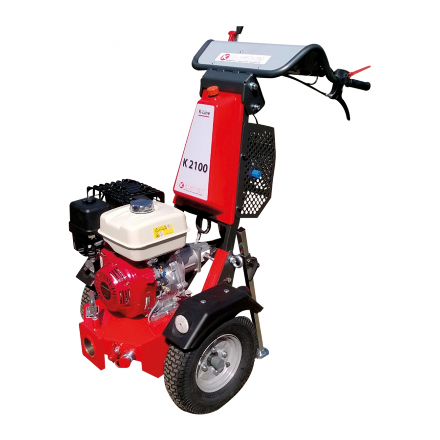
Hydrostatic Two Wheel Tractor
Order number: B00007
Manufactures by
Kersten Arealmaschinen GmbH
Empeler Straße 95
D - 46459 Rees
www.kersten-maschinen.de
Original operating
instructions
K 2100
From machine No.: 50202
Rev.: 01 Version: 12.04.2012
Distributed in UK by
Kersten (UK) Ltd Tel. 0118 986 9253
Progrees House 39 Boulton Road
Reading, RG2 0NH
www.kerstenuk.com - info@kerstenuk.com
Advertisement
Table of Contents

Related Manuals for Kersten K 2100


Summary of Contents for Kersten K 2100
- Page 1 Order number: B00007 From machine No.: 50202 Rev.: 01 Version: 12.04.2012 Distributed in UK by Manufactures by Kersten (UK) Ltd Tel. 0118 986 9253 Kersten Arealmaschinen GmbH Progrees House 39 Boulton Road Empeler Straße 95 D - 46459 Rees Reading, RG2 0NH www.kersten-maschinen.de...
-
Page 2: Table Of Contents
Table of Contents LETTER ............................3 ABOUT THESE OPERATING MANUAL ................... 4 BEFORE COMMISSIONING ............................NOTES ABOUT THIS MANUAL ........................... SAFETY INSTRUCTIONS FOR HYDROSTATIC SINGLE TOWERS ..........5 INTENDED USE................................GENERAL SAFETY AND ACCIDENT PREVENTION RULES ..................USED PICTOGRAMS ..............................WARNINGS AND SAFETY INSTRUCTIONS FOR FILLED LEAD - ACID BATTERIES .......... -
Page 3: Letter
Introduction Dear Customer, Thank you for choosing a quality product from Kersten. This product has been manufactured according to the most up-to-date production methods and extensive quality assurance measures, because only when you are satisfied with your device, our goal is reached. -
Page 4: About These Operating Manual
As self-propelled implements and implements can cause serious accidents or hazards if used improperly, a briefing of competent and authorized persons is mandatory when commissioning the Kersten implement for the first time. The best way to familiarize yourself with its basic functions and its handling is to choose a free and level terrain for your first trip. -
Page 5: Safety Instructions For Hydrostatic Single Towers
Safety instructions Safety instructions for hydrostatic towed tractors The most important safety instructions in this manual cannot cover all possibilities. It goes without saying that common sense and caution are factors that are not built into a machine, but must be brought by the person who uses and maintains the machine In order to keep the accident risk as low as possible, please observe the following subchapters. - Page 6 Safety instructions • Do not make any changes to the engine's upper idle speed. Too high a speed increases the risk of accidents. • Unauthorized conversions that endanger the operational safety of the machine are prohibited! • Check the machine for operational safety before each use! 3.2.2 Work and danger area •...
-
Page 7: Safety Instructions
Safety instructions • If there is a risk of slipping on sloping ground, the implement carrier must be secured by an escort with a rod or a rope. The escort must be located above the vehicle at a sufficient distance from the work tools! For the helper, it is recommended to wear crampons. - Page 8 Safety instructions • Only use original spare parts from the manufacturer, as these comply with the technical requirements and thus the risk of accidents is minimized! • Cleaning with the high-pressure cleaner should be carried out so that the water jet is not held directly in bearings, turned parts, grease nipples, shaft seals, wheel hubs, etc.
-
Page 9: Used Pictograms
Safety instructions 3.3 Pictograms used Explanation of the pictograms used: Before commissioning read and observe the operating instructions and safety instructions. Switch off the engine and remove the spark plug connector before carrying out any repair, maintenance or cleaning work. Never open or remove protective devices while the engine is running! Touch machine parts only when they have come to a... -
Page 10: Warnings And Safety Instructions For Filled Lead - Acid Batteries
Safety instructions 3.4 Warnings and safety instructions for filled lead - acid batteries • Follow the instructions on the battery and in the operating instructions. • Use eye protection. • Keep children away from acid and battery. Explosion hazard: • When charging batteries, a highly explosive bang mixture is produced, so please note the following: •... -
Page 11: Instructions For Use For Starter Batteries
Safety instructions 3.5 Instructions for Use for Starter Batteries 1. Removal and installation of the battery • Before removing the battery, switch off the engine and all power consumers. • Avoid short circuits due to tools. • When removing, first disconnect the negative pole (-), then the positive pole (+). •... - Page 12 Safety instructions 5. Decommissioning • Store the battery in a cool place. • When decommissioning, disconnect the negative pole (-). • Regularly check the charge status of the battery and recharge if necessary.
-
Page 13: Disposal
Complaints must be confirmed by the company Kersten Area Machines GmbH. Wear parts are excluded from the warranty. Furthermore, the warranty expires due to improper operation, when performing no or incorrect maintenance work, when using inadmissible equipment and when using non-original spare parts. -
Page 14: The Operation Of The Self-Operating Workstation
Operation of the self-propelled implement Figure 7.1 Operation of the self-propelled implement 7.1 Start the engine • To start the engine, the drive lever (Fig.7.1, item 5) must be in the recess of the shift gate and the lever for the PTO (Fig.7.1, item 3) in the "off" position. If the levers are not in the position described above, the ignition of the engine is interrupted, and the engine does not start •... -
Page 15: Stopping The Internal Combustion Engine
Operation of the self-propelled implement The presetting of the speed and the preselection of the direction of travel may only be carried out when the single-axle system is at a standstill, by operating the lower lever (Fig.7.1) Respectively! • The throttle lever (Fig.7.1, item 6) influences the engine speed and thus also the driving speed. -
Page 16: Securing The Machine During Transport
Operation of the self-propelled implement • By loosening the upper screws and removing the lower screws (Fig.7.2, Pos.2) left and right on the handrail, it can be fixed in two other positions. The factory setting is the middle position. • If the height adjustment via the handrail is not sufficient, it is still possible to adjust the guide bar (Fig.7.3, item 1). -
Page 17: Maintenance
Maintenance Maintenance 8.1 General maintenance instructions • Personal injury or damage to the machine may occur. Check all safety-related parts before every use of the machine. • Oil changes must be made according to the recommendations of the respective engine manufacturer. •... -
Page 18: Maintenance After 20 Hours Of Operation Or Longer Service Life
Maintenance 8.3 Maintenance after 20 operating hours or longer downtime • At regular intervals and at the beginning and end of the season, the moving parts of the unit must be greased or oiled. • There is a grease nipple below the device receptacle on the basic unit, which it regularly lubricates. -
Page 19: Technical Specifications
Technical specifications Technical Data Technical Data Type K 2100 engine Honda gasoline engine power 6,6 kW (9 hp) Max. Torque 19,1 Nm / 2.500 rmp capacity 270 cc Upper idle speed 3.400 min spark plug NGK BPR 6 ES Engine oil approx. - Page 20 Technical specifications Technical Data Parking brake optionally mechanically switchable Handlebar height adjustable and vibration damped Steering Unavailable Standard values (max tire pressure 2 bar - risk of Tire pressure at: explosion) max. 2 bar 4.00 - 8 110 kg (without tires) 4.00-8 16x6,5-8 Weight of basic unit...
-
Page 21: Wiring Plan - Safety Device
Wiring diagram 10 Wiring Diagram - Safety Device Reserve technical changes! Name use Application - S1 Deadman lever - S2 Driving lever - S3 Hydraulic auxiliary drive - L+ L + ignition coil, engine - L- L mass... -
Page 22: Malfunction And Their Remedy
Fault cause and their rectification 11 Fault cause and their rectification This chapter describes in more detail the most important faults which can occur during operation on the self-propelled implement. Faults which require major intervention must always be rectified by your specialist workshop. Observe safety instructions! Malfunction: Possible causes:... - Page 23 Disruptions and their rectification Malfunction: Possible causes: Remedy: Gasoline engine: Clean governor linkage - Reglergestänge verschmutzt, Gasoline engine klemmt arbeitet unregel- Mäßig - Engine stop line defective, Gasoline engine Leitung und Steckverbindungen - Missing sizes geht in Stoppstel- prüfen Massekontakt prüfen lung nicht aus - Air filter dirty Gasoline engine...
-
Page 24: Ec - Declaration Of Conformity
Produkt produit that the product produkt Einachsschlepper Porte-Outils Tool Carrier Werktuigdrager K 2100 G - GE satisfait à l'ensemble mit allen einschlägigen fulfiles all relevant voldoet aan alle Bestimmungen der de la directive machines provisions of Directive toepasselijke be- 2006/42/CE. - Page 25 Trevor Thorp Area Sales Manager North m: 07808 644007 Richard Wilkins Area Sales Manager South m: 07808 206496 Distributed in UK by Kersten (UK) Ltd Tel. 0118 986 9253 Progrees House 39 Boulton Road Reading, RG2 0NH www.kerstenuk.com - info@kerstenuk.com...
Need help?
Do you have a question about the K 2100 and is the answer not in the manual?
Questions and answers