Table of Contents
Advertisement
Instruction and Parts Manual
___________________________________________________
_
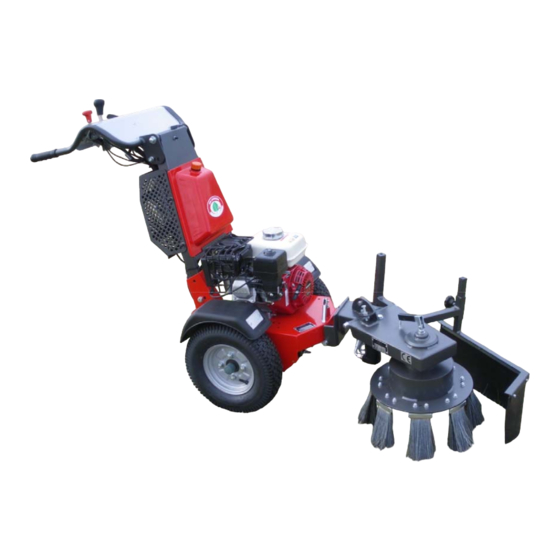
K1500
2 Wheel Hydraulic Tractor
Part no 6000 000 002 Copyright Kersten (UK) Ltd © 2010
Compiled 12/4/10
Kersten Maschinenvertriebs GmbH
Kersten (UK) Ltd
UK
D - 46459 Rees, Empeler Straße 93-95
Progress House, 39 Boulton Road
www.kersten-maschinen.de
Reading, Berkshire RG2 0NH
Tel.: 028 51 / 92 34 0
Fax: 028 51 / 92 34 44
Phone: 0118 986 9253
Email: info@cnect2.com
Advertisement
Table of Contents

Related Manuals for Kersten K1500


Summary of Contents for Kersten K1500
- Page 1 Instruction and Parts Manual ___________________________________________________ K1500 2 Wheel Hydraulic Tractor Part no 6000 000 002 Copyright Kersten (UK) Ltd © 2010 Compiled 12/4/10 Kersten Maschinenvertriebs GmbH Kersten (UK) Ltd D - 46459 Rees, Empeler Straße 93-95 Progress House, 39 Boulton Road www.kersten-maschinen.de...
-
Page 2: Table Of Contents
Contents Contents Forward About this manual Product identification Before operating Notes on using this manual Heath and safety Intended use General health and safety and accident prevention advice 3.2.1 General principles 3.2.2 Safe working area and hazard area 3.2.3 Prior to commencing work 3.2.4 Starting the machine 3.2.5... -
Page 3: Forward
Forward Forward Dear Sir, Madam, Thank you for purchasing a quality product the company Kersten. This product is designed and produced using the most modern manufacturing techniques and extensive quality assurance measures. It is only when you are satisfied with your product that our goal is achieved. -
Page 4: About This Manual
About this manual About this manual Product Identification Always quote model number and serial number when ordering spare parts. The identification plate may be found on the main chassis of all machines. Before operating Before you start the engine or attempt to attach or operate any machine, we ask that you urgently to make yourself familiar with the manual and the operation of the machine. -
Page 5: Notes On Using This Manual
About this manual Notes on using this manual All points to be considered are indicated as follows: ● Text ● Text ● Text Procedural instructions are indicated as follows: Text Text Text The machines described in this manual are subject continual to technical proress. -
Page 6: Intended Use
Health and Safety Health and safety It is important to note that not all possibilities can be covered within this manual. The manual assumes that the operator has a general awareness for Health and Safety to have been appointed an operator in the first place. This machine has been designed, so far as is reasonably practical, so that it will not endanger the safety of the operator or anyone else if the machine is used and maintained according to the instructions stated in this manual which... -
Page 7: Safe Working Area And Hazard Area
Health and Safety ● Before starting operating this machine you should be familiar with all controls and their functions. Familiarization should not be carried out during operation. It is too late! ● Beware of rotating parts—keep safe distance. ● Beware of trailing machines and machines with inertia. Ensure they stop completely before making any adjustments. -
Page 8: Starting The Machine
Health and Safety 3.2.4 Starting the machine ● When starting the machine all drives must be in the disengaged/off position. ● Do not run engines indoors. ● Be aware of flammable fluids if jump starting cables are used. Avoid explosion! 3.2.5 Whilst operating the machine ●... -
Page 9: Wheels And Tyres
Health and Safety 3.2.7 Wheels and tyres ● Before working on the wheels ensure the machine has been fully disabled. ● Always choc the wheels to prevent the machine from rolling. ● Regularly check wheel nuts for tightness and retighten if necessary. ●... -
Page 10: Cleaning, Maintenance And Repair Work
Health and Safety 3.2.9 Cleaning, maintenance and repair work ● The machine should be maintained according to the instructions contained within the manual. ● All controls, engine and functions must be cleaned regularly. ● Before attempting to clean or maintain any part of a machine, ensure the machine is stopped and has come to a rest and the power unit and any PTO is disabled. -
Page 11: Electrical System And Equipment
Health and Safety ● Whenever handling fuel there is an increased risk of fire. Never refill near a naked flame or sparks. Do not smoke! ● Oils, fuels and filters should be disposed of separately using a compliant method. ● Do not refuel in confined spaces. -
Page 12: Safety Decals
Health and safety 3.3 Safety Decals ● This machine is equipped with warning symbols (safety decals). ● These decals indicate types and areas of endangerment and in particular the safety measure which should be taken. ● Always remain alert and conscious of the dangers the decals indicate on the machine, you are operating, presents to you and others. - Page 13 Health and safety There is a risk of injury. Ensure all machine parts have been stopped and come to a complete rest before attempting to carry out inspection or maintenance. There is a risk of injury from flying objects being ejected from the machine.
-
Page 14: Disposal
This device must be disposed of according to the regulation of the municipality or the country. All possible parts should be recycled and the remainder disposed of in a satisfactory manner. The company Kersten Maschinenvertriebs GmbH or Kersten (UK) Ltd does not take responsibility of disposal. Warranty The manufacturer guarantees its products for 12 months from the date of delivery. -
Page 15: Recommendations
Recommendations Recommendations 6.1 Lubricants For engine and transmission lubricants please see “technical specification section” of this manual and separate engine manufacturers instruction manual. For "open" or nipple lubrication points, we recommend a bio-degradable manufactured from organic compounds. We recommend the use of biolubricants where possible. - Page 16 $ ( & < & " < < * < &: 1 "# 6 1 / 0.*' 1 "# < 5 3 / ! 5 *' H 3 8 1 < G " & * < < !!( 1 % " !$ "...
- Page 17 $ & ' < " " M " < " " " < < * < " < " C " ;* + < ) < < < < < "0 " < " " " < / " < <...
- Page 18 & & ' / ' * " " ? " " " < " 0 > " " " " < / < / " < " " " 1 N O 0 " > < " ? ? < 1 / * "...
- Page 19 ;* 6 ( " ) < < " < C * ? < 8 * < / " " "8 < . < < " " < " " < ? < / " ? " ? " ? ? $ <...
- Page 20 ;* 4 "8 8 < < < 9 ! 8 & " < " < < < < / 0 ) "<...
- Page 21 & & & ( ( ' ?* + " " " " < " " 8 < " " " < 5 < < ' < ; " ? < < 8 < < < ' < < " * <...
- Page 22 < < < < < 2 6 6 , + & 3 8 " " ? < 0 ; < " < < !."" < < < " * " $ & ' ( < < < * " > <...
- Page 23 ! < . " @ EG Konformitätserklärung entsprechend der EG-Richtlinie 98/37 EG Der Inverkehrbringer Kersten Maschinenvertriebs GmbH Empeler Straße 93 – 95 D – 46459 Rees erklärt in alleiniger Verantwortung, dass das Produkt K1500 auf das sich diese Erklärung bezieht, den einschlägigen grundlegenden Sicherheits- und Gesundheitsanforderungen der EG Richtlinie 98/37/EG entspricht.
- Page 24 K 1500 Zusammenbau Stand 20.10.2009 C00162 AKX...
- Page 25 K 1500 Zusammenbau Stand 20.10.2009 C00162 AKX Art.-Nr. Anz. Benennung C00011 Basic chassis KDM 35 Management jamb short, steamed, small tank C00176 simple filter gland C00002 Panel toggle valve, single lever C00161 Driving motor KDM 35 Assembly C00007 Differential axis with Center drive KDM 35 / 70 C00003 Hydraulic control for Fahr &...
- Page 26 Grundgehäuse KDM 35 Zusammenbau Stand 30.09.2009 C00011 AGX Art.-Nr. Anz. Benennung C00011 Basic chassis KDM 35 700 500 050 Holder fenders 901 208 020 Senkkopfschr. with inside Skt.. 926 900 001 Fender set 950 900 070 Plate 932 261 223 Bulkhead socket 932 161 323 Bulkhead connectors...
- Page 27 Fahrantrieb KDM 35 Zusammenbau Stand 30.09.2009 C00164 ADX Art.-Nr. Anz. Benennung C00012 Hydraulic motor production console 903 012 100 Eye bolt 905 112 000 U disk 900 012 002 Stop nut 901 012 055 Skt.-screw 920 101 648 Drive chain Hydraulic motor connected to the 935 111 040 page...
- Page 28 Differentialachse mit Mittenantrieb KDM 35/70 Zusammenbau Stand 30.09.2009 C00007 AAX Art.-Nr. Anz. Benennung 924 100 205 Ball SB 205 924 200 205 Bearing shells set siehe Reifenliste 908 047 440 Key 4, 76 x 4 76 x 40 mm 905 820 000 Bensingring C00015 Lagerbuchse long...
- Page 29 Feststellbremse für K-Serie Stand 30.09.2009 C00018 AZX Art.-Nr. Anz. Benennung 908 612 018 Kpl pipe clamp. 18 mm 700 005 003 Rod brake system 700 005 004 Brake 700 005 005 Lever C00017 Brake rod holder right C00016 Brake rod holder left 903 108 030 Eye bolt 909 200 021...
- Page 30 Hydrauliksteuerung für Fahr- & Nebenantrieb Stand 20.09.2009 C00003 AHX Art.-Nr. Anz. Benennung Art.-Nr. Anz. Benennung 12 909 200 124 Spring Z 124FI Cultivation plate motor & 700 500 051 13 937 125 030 18-Er piston seal Kit " 14 900 106 000 U disk Running &...
- Page 31 Bedienkonsole, Umschaltventil und Einfachhebel Stand 05.10 .2009 C00002 ABX...
- Page 32 Bedienkonsole, Umschaltventil und Einfachhebel Stand 05.10.2009 C00002 ABX Art.-Nr. Anz. Benennung Art.-Nr. Anz. Benennung Hand jamb kompl. without 26 905 105 000 U disk C00042 steering lever 27 960 041 000 Polar Cap C00043 Panel of switching valve 28 767 000 074 2-Wire cable Valve holder for switching 29 901 005 025...
- Page 33 Hydraulikschema K1500 Stand 14.09.2009 C00177 AHX...
- Page 34 Stückliste - Hydraulikschema K1500 Stand 14.09.2009 C00177 AHX Art.-Nr. Anz. Benennung 930 763 001 Hydraulic hose 930 763 002 Hydraulic hose 930 700 004 Hydraulic hose 930 700 010 Hydraulic hose 930 764 003 Hydraulic hose 930 764 004 Hydraulic hose...
- Page 35 Honda Motor 6,5PS mit 3,1 ccm Pumpe Stand 07.08.2009 C00159 AVX Art.-Nr. Anz. Benennung 920 000 012 Honda Motor 6,5PS 2a-2e 934 301 762 Bellhousings, kompl. 925 101 024 Coupling socket Z 24 705 350 508 Crankshaft Jack 4a-d 934 100 029 Hydraulic pump kompl.
- Page 36 Zubehör Radgewichte Stand 09.10.2009 C00122 AZX Art.-Nr. Anz. Benennung 945 104 008 Wheel weight 905 112 000 U disk 905 012 000 Spring ring 901 012 060 Skt.-screw 902 812 040 Threaded sleeve...
- Page 37 Block 926 141 408 K1100 4.00-8 Block 926 140 408 712 000 022 4.00-8 Ackerstollen 926 110 408 712 000 022 K1500 4.00-8 Block 926 140 408 700 000 022 4.00-8 Ackerstollen 926 110 408 712 000 022 K1750 4.00-8...
- Page 40 Your contact at Kersten UK: Christopher Faulkner, Managing Director Sean Faulkner, Sales Manager Trevor Thorp, Area Sales Manager North Kersten UK are the sole UK distributor of the Meyer range of snow management equipment. Separate catalogue available upon request. Telephone: 0118 986 9253 Kersten (UK) Ltd, Progress House, 39 Boulton Road, Reading RG2 0NH www.kersten-machines.com...
Need help?
Do you have a question about the K1500 and is the answer not in the manual?
Questions and answers