Table of Contents
Advertisement
Available languages
Available languages
Disclaimer
The information in this document is subject to change without notice. The
manufacturer makes no representations or warranties with respect to the contents
hereof and specifically disclaims any implied warranties of merchantability or
fitness for any particular purpose. The manufacturer reserves the right to revise this
publication and to make changes from time to time in the content hereof without
obligation of the manufacturer to notify any person of such revision or changes.
Federal Communications Commission (FCC)
This equipment has been tested and found to comply with the limits for a Class B
digital device, pursuant to Part 15 of the FCC Rules. These limits are designed to
provide reasonable protection against harmful interference in a residential
installation. This equipment generates, uses, and can radiate radio frequency
energy and, if not installed and used in accordance with the instructions, may cause
harmful interference to radio communications. However, there is no guarantee that
interference will not occur in a particular installation. If this equipment does cause
harmful interference to radio or television reception, which can be determined by
turning the equipment off and on, the user is encouraged to try to correct the
interference by one or more of the following measures:
•
Reorient or relocate the receiving antenna
•
Increase the separation between the equipment and the receiver
•
Connect the equipment onto an outlet on a circuit different from that to
which the receiver is connected
•
Consult the dealer or an experienced radio/TV technician for help
Shielded interconnect cables and a shielded AC power cable must be employed with
this equipment to ensure compliance with the pertinent RF emission limits
governing this device. Changes or modifications not expressly approved by the
system's manufacturer could void the user's authority to operate the equipment.
Declaration of Conformity
This device complies with part 15 of the FCC rules. Operation is subject to the follow-
ing conditions:
•
This device may not cause harmful interference.
•
This device must accept any interference received, including interference
that may cause undesired operation.
This device is in conformity with the following EC/EMC directives:
EN 55032
EN 61000-3-2
EN 61000-3-3
EN 55024
EN 60950
CE marking
Electromagnetic compatibility of multimedia equipment - Emission
requirements
Electromagnetic Compatibility(EMC)
Part 3-2: Limits-Limits for harmonic current emissions (equipment input
current 16A per phase)
Electromagnetic Compatibility(EMC)
Part 3-3: Limits-Limitation of voltage changes, voltage fluctuations and flicker
in public low-voltage supply systems, for equipment with rated current 16A
per phase and not subject to conditional connection
Information technology equipment-Immunity characteristics-Limits and
methods of measurement
Safety for information technology equipment including electrical business
equipment
APLD-I USER MANUAL
Advertisement
Table of Contents

Related Manuals for ECS APLD-I


Summary of Contents for ECS APLD-I
-
Page 1: Declaration Of Conformity
16A per phase and not subject to conditional connection Information technology equipment-Immunity characteristics-Limits and EN 55024 methods of measurement Safety for information technology equipment including electrical business EN 60950 equipment CE marking APLD-I USER MANUAL... -
Page 2: Table Of Contents
TABLE OF CONTENTS Preface Brief Introduction Specifications..................1 Motherboard Components..............3 Header Pin Definition and Jumper Settings.........5 I/O Ports....................8 Multi-language Quick Installation Guide English....................9 Simplified Chinese................11 Korean......................13 Indonesian.....................15 Japanese....................17 Vietnamese..................19 APLD-I USER MANUAL... -
Page 3: Brief Introduction
1 x Printer header • 1 x Amplifier Speaker header Note: VGA port(real panel I/O) + DC_IN port(real panel I/O) and DP port (real panel I/O) + ATX_POWER header(internal I/O header) are alternative options of the motherboard. APLD-I USER MANUAL... - Page 4 - F7 hot key for boot up devices option - Add BIOS parameters and copy to USB Flash Drive Form Factor • Mini ITX Size, 170mm x 170mm QR Code for the complete manual download on ECS website: http://www.ecs.com.tw APLD-I USER MANUAL...
-
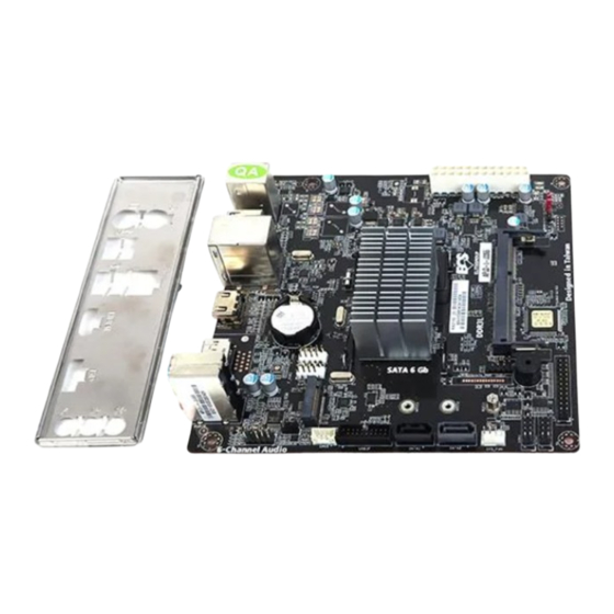
Page 5: Motherboard Components
Motherboard Components APLD-I USER MANUAL... - Page 6 20. F_USB1~2 Front panel USB 2.0 headers 21. BT Battery Note: VGA port(real panel I/O) + DC_IN port(real panel I/O) and DP port (real panel I/O) + ATX_POWER header(internal I/O header) are alternative options of the motherboard. APLD-I USER MANUAL...
-
Page 7: Header Pin Definition And Jumper Settings
Data Set Ready Ground Data Terminal Ready Serial Output Serial Input Data Carrier Detect F_USB1~2 USB Port B (+) USB Port B (-) Ground Power +5V Power +5V USB Port A (-) Ground USB Port A (+) SPKR Signal APLD-I USER MANUAL... - Page 8 Chassis cover Chassis cover is removed is closed LPC Signal Power +3.3V LPC Signal LPC signal LPC Signal Reset LPC Signal Clock Ground SLCT Ground Ground BUSK Ground Ground Ground Ground Ground Ground SLCT INIT ERROR STROBE APLD-I USER MANUAL...
- Page 9 USB3 ICC Port2 SuperSpeed Rx+ USB3 ICC Port2 SuperSpeed Rx- Front Panel USB Power MONO Jumper 1-2: Stereo 2-3: Mono MONO CLR_CMOS Jumper 1-2: NORMAL 2-3: CLEAR CMOS Before clearing the CMOS, make sure to turn off the system. CLR_CMOS APLD-I USER MANUAL...
-
Page 10: I/O Ports
12. VGA Port* (optional) Connect your monitor to the VGA port. Note: VGA port(real panel I/O) + DC_IN port(real panel I/O) and DP port (real panel I/O) + ATX_POWER header(internal I/O header) are alternative options of the motherboard. APLD-I USER MANUAL... -
Page 11: Multi-Language Quick Installation Guide
Hardware Installation Guide Installation Steps Step 1. Installation of Memory Modules: 1-1. Align the cutouts on the DIMM 1-2. Insert the memory module to the module edge connector to the notches slot and press it down until it seats in the DIMM slot. correctly. - Page 12 Step 4. Connecting Cables and Power Connectors: a. Connect the SATA hard drive to its b. Connect SATA power connector to the SATA cable SATA device c. Connect 24-pin power cable Please note that when installing 24-pin power cable, the latches of power cable and the ATX connector match perfectly.
-
Page 13: Simplified Chinese
硬件安装指南 安装步骤 1.安装记忆体模组: 1-1. 将DIMM模块边缘连接器上的切口 1-2. 将内存模块插入插槽和向下按直至 与DIMM插槽中的凹槽对齐。 其正确就位。 确保插槽锁扣紧贴DIMM 模块的边缘。 2-1. 取下机箱后面的I/O挡板,换上主 2-2. 将主板的后I/O对准机箱上的I/O挡板孔 板附带的I/O弹片。 位,放入机箱并以螺丝固定。 VGA端口(实际面板I / O)+ DC_IN端口(实际面板I / O)和DP端口(实际 面板I / O)+ ATX_POWER头(内部I / O头)是可选的选项的主板。 移除机箱后面的扩充金属挡板,确认扩充卡完全插入扩展 槽后,重新拧上螺丝。... - Page 14 4.连接电源线与电源接头: a. 将SATA电缆连接至SATA 硬盘 b. 将SATA电源接头连接至SATA设备 c. 连接24针电源线与电源接头 请注意电源接头与电源线必须完全扣合 VGA端口(实际面板I / O)+ DC_IN端 口(实际面板I / O)和DP端口(实际 面板I / O)+ ATX_POWER头(内部I / O 头)是可选的选项的主板。 5.连接机箱端口: 当上述安装步骤完成后,请开始安装键盘,鼠标, 显示器等外围设备,然后连接电 源并启 动系统。请安装好所需的软件。 BIOS使用设定 BIOS程序画面会显示系统配置,同时提供操作选项让您设定系统参数。当开机时, BIOS会进行开机自我测试 (POST),请点击 <D EL> 或 F2 进入BIOS程序设定。第一次 开机时,POST画面可能会显示 信息,请进入BIOS选单 并选 将BIOS重新设定为默认值...
-
Page 15: Korean
하드웨어 설치 가이드 단계별 설치 방법 1단계. 메모리 모듈 설치하기: 1-1. DIMM 모듈 에지 커넥터의 컷 아웃을 1-2. 메모리 모듈을 슬롯에 삽입하고 올바르게 DIMM 슬롯의 노치에 맞 춥니 다. 장착 될 때까지 아래로 누르십시오. 슬롯 래치가 DIMM 모듈의 모서리에 달라 붙지 않도록하십시오. - Page 16 4단계. 케이블 및 전원 커넥터 연결하기: a. SATA 하드 드라이브를 SATA b. SATA 전원 커넥터를 SATA 장치에 연결합 케이블에 연결합니다 니다 c. 2 4 핀 전원 케이블을 연결합니다 24핀 전원 케이블 연결시 전원 케이블과 ATX 커넥터의 걸쇠가 완벽하게 맞아야 합니다. VGA 포트...
-
Page 17: Indonesian
Panduan Pemasangan Perangkat Keras Langkah-Langkah Pemasangan Langkah 1. Pemasangan Modul Memori: 1-1. Sejajarkan guntingan pada modul DIMM 1-2. Masukkan modul memori ke slot dan konektor tepi ke takik di slot DIMM. tekan ke bawah sampai itu kursi dengan benar. Pastikan kait slot yang melekat pada tepi modul DIMM. - Page 18 Langkah 4. Menyambungkan Kabel dan Konektor Daya: a. Sambungkan hard drive SATA ke kabel b. Sambungkan konektor daya SATA ke SATA perangkat SATA c. Sambungkan kabel daya 24 pin kabel daya 24, kait pada kabel daya dan konektor ATX harus sesuai. Port VGA (panel aktual I / O) + pelabuhan DC_IN (panel aktual I / O) dan port DP (Panel aktual I / O) +...
-
Page 19: Japanese
ハードウェアインストールガイド インストール手順 手順 1 メモリモジュールのインストール: 1-1. DIMMモジュールのエッジコネクタの切り 2-2. メモリモジュールをスロットに挿入し、それ 欠きをDIMMスロットのノッチに合わせます。 が正しく座るまで押し下げます。 スロットのラッ チがDIMMモジュールの端にしっかりとはまっ ていることを確認します。 手順 2 マザーボードのインストール: 3-1. ケースの背面I/Oプレートをマザーボ 3-2. I/Oプレートにマザーボードを位置決め ードに付属のI/Oシールドと交換します。 し、ケース内に配置します。ネジでマザーボー ドをケースに固定します。 VGAポート(実パネルI / O)+ DC_INポート(実パネルI / O)およびDPポート (実パネルI / O)+ ATX_POWERヘッダー(内部I / Oヘッダー)は代替です マザーボードのオプション。 手順 3 ストレージデバイスのインストール: フロントカバーと5.25インチのプレートをケースから取り外します。ストレージデバイス... - Page 20 手順5 ケーブルと電源コネクタの接続: a. IDEハードドライブにIDEケーブルを接 b. SATAハードドライブにSATAケーブル 続します を接続します c. 24ピン電源ケーブルを接続します 24ピン電源ケーブルを接続するとき、電源 ケーブルのラッチとATXコネクタが適合す ることを確認してください。 VGAポート(実パネルI / O)+ DC_INポート (実パネルI / O)およびDPポート (実パネルI / O)+ ATX_POWERヘッダー (内部I / Oヘッダー)は代替です マザーボードのオプション。 手順6 ケース上のポートに接続: 背面パネルは図と異なる場合があります。マザーボードによって異なります。 上記の手順を完了した後、キーボードやマウスなどの周辺機器を接続してください。その後電源 を接続し、システムを起動します。必要なソフトウェアをすべてインストールしてください。周 辺機器をすべてインストールしてください。 BIOSの使用 BIOS(基本入出力システム)セットアップユーティリティはシステムの構成状態を表示し、 システムパラメータ設定のオプションを提供します。システムを起動すると、BIOSが POSTという診断テストのルーチンを実行します。セットアップを開始するには<DEL>ま たはF2を押してください。初めて電源を投入したとき、POST画面に「CMOS Set- tings...
-
Page 21: Vietnamese
Hướng Dẫn Lắp Đặt Phần Cứng Các Bước Lắp Đặt Bước 1. Lắp Các Mô-đun Bộ Nhớ: 1-1. Căn xảo trên các kết nối cạnh mô-đun 1-2. Chèn module bộ nhớ với khe cắm và DIMM để các bậc trong các khe cắm DIMM. bấm nó... - Page 22 Bước 4. Nối Dây Cáp và Đầu Nối Điện: a. Nối ổ cứng SATA với dây cáp SATA b. Nối đầu nối điện SATA với thiết bị của nó. SATA c. Nối dây cáp nguồn 24 chân Vui lòng lưu ý rằng khi lắp cáp nguồn 24 chân, các chốt của cáp nguồn và...
Need help?
Do you have a question about the APLD-I and is the answer not in the manual?
Questions and answers