Table of Contents
Advertisement
Copyright
This publication, including all photographs, illustrations and software, is protected
under international copyright laws, with all rights reserved. Neither this manual, nor
any of the material contained herein, may be reproduced without written consent of
the author.
Version 3.0
Disclaimer
The information in this document is subject to change without notice. The manufac-
turer makes no representations or warranties with respect to the contents hereof
and specifically disclaims any implied warranties of merchantability or fitness for
any particular purpose. The manufacturer reserves the right to revise this publica-
tion and to make changes from time to time in the content hereof without obligation
of the manufacturer to notify any person of such revision or changes.
Trademark Recognition
Microsoft, MS-DOS and Windows are registered trademarks of Microsoft Corp.
AMD, Phenom, Athlon, Sempron, Turion, and Duron are registered trademarks of AMD
Corporation.
Other product names used in this manual are the properties of their respective owners
and are acknowledged.
Federal Communications Commission (FCC)
This equipment has been tested and found to comply with the limits for a Class B
digital device, pursuant to Part 15 of the FCC Rules. These limits are designed to
provide reasonable protection against harmful interference in a residential instal-
lation. This equipment generates, uses, and can radiate radio frequency energy and,
if not installed and used in accordance with the instructions, may cause harmful
interference to radio communications. However, there is no guarantee that interfer-
ence will not occur in a particular installation. If this equipment does cause harmful
interference to radio or television reception, which can be determined by turning
the equipment off and on, the user is encouraged to try to correct the interference by
one or more of the following measures:
•
Reorient or relocate the receiving antenna
•
Increase the separation between the equipment and the receiver
•
Connect the equipment onto an outlet on a circuit different from that to
which the receiver is connected
•
Consult the dealer or an experienced radio/TV technician for help
Shielded interconnect cables and a shielded AC power cable must be employed with
this equipment to ensure compliance with the pertinent RF emission limits govern-
ing this device. Changes or modifications not expressly approved by the system's
manufacturer could void the user's authority to operate the equipment.
A55F-M4 USER MANUAL
Preface
Advertisement
Table of Contents

Subscribe to Our Youtube Channel
Related Manuals for ECS A55F-M4


Summary of Contents for ECS A55F-M4
- Page 1 Shielded interconnect cables and a shielded AC power cable must be employed with this equipment to ensure compliance with the pertinent RF emission limits govern- ing this device. Changes or modifications not expressly approved by the system’s manufacturer could void the user’s authority to operate the equipment. A55F-M4 USER MANUAL...
-
Page 2: Declaration Of Conformity
Describes the ATI Crossfire page 57 Technology CrossFire Technology (AMD Dual Graphics) Support Chapter 6 Provides information about page 61 Setting Up AMD A55 RAID SATA RAID Setup Configuration Chapter 7 page 69 Provides basic trouble Trouble Shooting shooting tips. A55F-M4 USER MANUAL... -
Page 3: Table Of Contents
The Standard Configuration...........25 Entering the Setup Utility............25 Resetting the Default CMOS Values........26 Using BIOS..................26 BIOS Navigation Keys..............27 Main Menu................28 Advanced Menu..............29 Chipset Menu................42 M.I.B III(MB Intelligent Bios III) Menu........44 Boot Menu................45 Security Menu.................47 Exit Menu................50 Updating the BIOS..............51 A55F-M4 USER MANUAL... - Page 4 Chapter 4 Using the Motherboard Software Auto-installing under Windows XP/7/8........53 Running Setup...............53 Manual Installation................55 ECS Utility Software (Intelligent EZ Utility)........55 Chapter 5 CrossFire Technology [AMD Dual Graphics] Support CrossFire Technology..............57 Chapter 6 Setting Up AMD A55 RAID Configuration Setting Up a Bootable RAID Array..........61...
-
Page 5: Introducing The Motherboard
Chapter 1 Introducing the Motherboard Introduction Thank you for choosing the A55F-M4 motherboard. This motherboard is a high per- formance, enhanced function motherboard that supports socket FM1 for AMD A series processor for high-end business or personal desktop markets. The motherboard is based on AMD A55 (Hudson D2) express chipset for best desktop platform. -
Page 6: Specifications
Specifications • Socket FM1 for AMD A series processors • Supports CPU up to 100W TDP Note: Please go to ECS website for the latest CPU support list. Chipset • AMD A55 Chipset Memory • Dual-channel DDR3 memory architecture •... - Page 7 • AMI BIOS with 32Mb SPI Flash ROM System BIOS - Supports ECS MIB III Utility - Supports Plug and Play, STR(S3)/STD(S4) - Supports Hardware Monitor - Supports ACPI 3.0 version & DMI - Audio, LAN, can be disabled in BIOS...
-
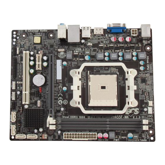
Page 8: Motherboard Components
Motherboard Components A55F-M4 USER MANUAL... - Page 9 17. PCIE1 PCI Express x1 slot 18. CASE1 Case open header 19. PCIEX16 PCI Express slot for graphics interface 20. F_AUDIO Front panel audio header 21. USBPWR_R Rear USB/PS2 power select jumper 22. ATX12V 4-pin +12V power connector A55F-M4 USER MANUAL...
-
Page 10: I/O Ports
It can be connected to an external CD/DVD player, Tape player or other audio devices for audio input. 8. Line-out(lime) It is used to connect to speakers or headphones. 9. Microphone(pink) It is used to connect to a microphone. A55F-M4 USER MANUAL... -
Page 11: Installing The Motherboard
Place the motherboard over the mounting brackets and secure the motherboard onto the mounting brackets with screws. Do not over-tighten the screws as this can stress the motherboard. A55F-M4 USER MANUAL... -
Page 12: Checking Jumper Settings
2. Make sure the power supply provides enough 5VSB voltage before selecting the 5VSB function. 3. It is required that users place the USBPWR_F1 & USBPWR_R1 cap onto 2-3 pin rather than 1-2 pin as default if you want to wake up the computer by USB/ PS2 KB/Mouse. A55F-M4 USER MANUAL... -
Page 13: Installing Hardware
Pull up the lever away from the socket and lift up to 90-degree angle. Locate the CPU cut edge (the corner with the pin hold noticeably missing). Align and insert the CPU correctly. Press the metal lever back into its original position. A55F-M4 USER MANUAL... -
Page 14: Installing The Cpu Cooler
CPU, and make it to be a thin layer. B. Put the CPU Fan down on the retention module and flip the levers over the heat sink in place. C. Connect the CPU cooler power connector to the CPU_FAN connector. A55F-M4 USER MANUAL... -
Page 15: Installing Memory Modules
DIMM slot. The slot latches are levered upwards and latch on to the edges of the DIMM. *Due to the limitation of chipset spec, it supports up to 1866 MHz for motherboard with a single DIMM per channel. A55F-M4 USER MANUAL... -
Page 16: Installing Add-On Cards
ISA bus standard. The PCI slot on this board is PCI v2.2 compliant. Before installing an add-on card, check the documentation for the card care- fully. If the card is not Plug and Play, you may have to manually configure the card before installation. A55F-M4 USER MANUAL... - Page 17 2. The onboard PCI interface does not support 64-bit SCSI cards. Please refer the following illustrations to install the add-on card: Install the LAN Card in the PCIE X1 slot Install the VGA Card in the PCI slot Install the VGA Card in the PCIE X16 slot A55F-M4 USER MANUAL...
-
Page 18: Connecting Optional Devices
SATA1~4 connectors are used to support the Serial ATA 3.0Gb/s device, simpler disk drive cabling and easier PC assembly. It eliminates limitations of the current Paral- lel ATA interface. But maintains register compatibility and software compatibility with Parallel ATA. A55F-M4 USER MANUAL... - Page 19 Please make sure that the USB cable has the same pin assignment as indi- cated above. A different pin assignment may cause damage or system hang- 3. LPT: Onboard parallel port Header This is a header that can be used to connect to the printer, scanner or other devices. A55F-M4 USER MANUAL...
- Page 20 Connect a serial port extension bracket to this header to add a serial port to your system. 5. SPDIFO: SPDIF out header This is an optional header that provides an SPDIFO (Sony/Philips Digital Interface) output to digital multimedia device through optical fiber or coaxial connector. A55F-M4 USER MANUAL...
- Page 21 The front panel audio header allows the user to install auxiliary front-oriented mi- crophone and line-out ports for easier access. This header supports HD audio by default. If you want connect an AC’ 97 front panel audio to HD onboard headers, please set as below picture. A55F-M4 USER MANUAL...
- Page 22 AC’ 97 Front Panel, please don’ t tick off “Using Front Jack Detect ”. If you use HD Audio Front Panel, please tick off the option of “ Using Front Jack Detect ”. * For reference only A55F-M4 USER MANUAL...
-
Page 23: Installing A Sata Hard Drive
Attach either cable end to the connector on the motherboard. Attach the other cable end to the SATA hard drive. Attach the SATA power cable to the SATA hard drive and connect the other end to the power supply. * For reference only A55F-M4 USER MANUAL... -
Page 24: Connecting Case Components
FAN Power Connector) Connect the CPU cooling fan cable to CPU_FAN. Connect the system cooling fan connector to SYS_FAN. Users please note that the fan connector supports the CPU cooling fan of 1.1A ~ 2.2A (26.4W max) at +12V. A55F-M4 USER MANUAL... - Page 25 24-pin power cable Connecting 4-pin power cable The ATX12V4P power connector is used to provide power to the CPU. When installing 4-pin power cable, the latches of power cable and the ATX12V4P match perfectly. 4-pin power cable A55F-M4 USER MANUAL...
- Page 26 4. SPK: Speaker Connect the case speaker cable to SPK. A55F-M4 USER MANUAL...
-
Page 27: Front Panel Header
50 ms to signal the power supply to switch on or off. The time requirement is due to internal de-bounce circuitry. After receiving a power on/off signal, at least two seconds elapses before the power supply recognizes another on/off signal. This concludes Chapter 2. The next chapter covers the BIOS. A55F-M4 USER MANUAL... - Page 28 Memo A55F-M4 USER MANUAL...
-
Page 29: Using Bios
When you power on the system, BIOS enters the Power-On Self Test (POST) routines. POST is a series of built-in diagnostics performed by the BIOS. After the POST routines are completed, the following message appears: Press DEL to enter SETUP A55F-M4 USER MANUAL... -
Page 30: Resetting The Default Cmos Values
Other options lead to dialog boxes that prompt you for informa- tion. Some options (marked with an icon ) lead to submenus that enable you to change the values for the option. Use the cursor arrow keys to scroll through the items in the submenu. A55F-M4 USER MANUAL... -
Page 31: Bios Navigation Keys
Select the boot icon and press <Enter> or double click the left key of the mouse to display the screen. Then you can choose the boot device. Advanced Select the advanced icon and press <Enter> or double click the left key of the mouse to display the screen. A55F-M4 USER MANUAL... -
Page 32: Main Menu
The Date and Time items show the current date and time on the computer. If you are running a Windows OS, these items are automatically updated whenever you make changes to the Windows Date and Time Properties utility. A55F-M4 USER MANUAL... -
Page 33: Advanced Menu
: Select Screen /Click: Select Item Super IO Configuration Intel(R) Smart Connect Technology Enter/Dbl Click : Select +/- : Change Opt. F1: General Help F2: Previous Values F3: Optimized Defaults F4: Save & Exit ESC/Right Click: Exit A55F-M4 USER MANUAL... -
Page 34: Lan Configuration
Use this item to enable or disable UEFI network stack. Ipv4/6 PXE Support (Enabled) Use these items to enable or disable the Ipv4/6 PXE Boot support. If disabled IPV4/ 6 PXE boot option will not be created. Press <Esc> to return to the Advanced Menu page. A55F-M4 USER MANUAL... -
Page 35: Pc Health Status
If you choose Silent mode, the fan speed will be auto restricted to make system more quietly. If you choose Manual mode, the fan speed will be adjust depending on users’ parameters. A55F-M4 USER MANUAL... - Page 36 SMART Fan Start Offset(-) : Select Screen Tolerence Value /Click: Select Item Stop Value Enter/Dbl Click : Select +/- : Change Opt. F1: General Help F2: Previous Values F3: Optimized Defaults F4: Save & Exit ESC/Right Click: Exit A55F-M4 USER MANUAL...
- Page 37 System temperature, CPU & DIMM voltage, CPU & System fan speed... etc. • CPU Tct1 • CPU Fan Speed • System Fan Speed • CPU Voltage • DIMM Voltage • FCH Voltage Press <Esc> to return to the Advanced Menu page. A55F-M4 USER MANUAL...
-
Page 38: Power Management Setup
EUP Function (Enabled) This item allows user to enable or disable EUP support. Power LED Type (Dual Color LED) This item shows the type of the Power LED. Press <Esc> to return to the Advanced Menu page. A55F-M4 USER MANUAL... -
Page 39: Acpi Configuration
F4: Save & Exit ESC/Right Click: Exit ACPI Sleep State [S3(Suspend to RAM)] This item allows user to enter the ACPI S3 (Suspend to RAM) Sleep State (default). Press <Esc> to return to the Advanced Menu page. A55F-M4 USER MANUAL... -
Page 40: Cpu Configuration
This item is used to set the CPB mode. AMD C&Q (Enabled) This item enables or disables the CPU C&Q Function. SB Spread Spectrum (Enabled) This item enables or disables the SB Clock Spread Spectrum. Press <Esc> to return to the Advanced Menu page. A55F-M4 USER MANUAL... -
Page 41: Sata Configuration
SATA Port 1~4 (Not Present) This motherboard supports four SATA channels and each channel allows one SATA device to be installed. Use these items to configure each device on the SATA channel. Press <Esc> to return to the Advanced Menu page. A55F-M4 USER MANUAL... -
Page 42: Usb Configuration
All USB Devices (Enabled) Use this item to enable or disable all USB devices. Legacy USB Support (Enabled) Use this item to enable or disable support for legacy USB devices. Press <Esc> to return to the Advanced Menu page. A55F-M4 USER MANUAL... -
Page 43: Super Io Configuration
This item allows you to enable or disable serial port. Device Settings (IO=3F8h; IRQ=4) This item shows the information of the device settings. Change Settings (Auto) Use this item to change device settings. Press <Esc> to return to the Super IO Configuration page. A55F-M4 USER MANUAL... - Page 44 Use this item to change device settings. Device Mode (Standard Printer Mode) This item shows the information of the device mode. Press <Esc> to return to the Super IO Configuration page. Press <Esc> to return to the Advanced Menu page. A55F-M4 USER MANUAL...
-
Page 45: Intel Smart Connect Technology
Use this item to enable/disable ISCT WLAN Power Control. ISCT WWAN Power Control (Enabled) Use this item to enable/disable ISCT WWAN Power Control. ISCT Sleep Duration Value Format (Actual Time) Use this item to select actual time or duration in seconds. (ISCT 2.0) A55F-M4 USER MANUAL... -
Page 46: Chipset Menu
Initate Graphic Adapter (IGD) This item allows you to select graphics controller to use as the primary boot device. CrossFire (Enabled) This item allows you to enableb or disable CrossFire function. Press <Esc> to return to the Chipset Menu page. A55F-M4 USER MANUAL... - Page 47 This item indicates whether the case has been opened. Press <Esc> to return to the Chipset Menu page. NOTE: *This item will not appear if the motherboard doesnot have the HDMI port. Please take the actual BIOS for the standard. A55F-M4 USER MANUAL...
-
Page 48: Mb Intelligent Bios Iii) Menu
RAS# Active Time (tRAS) (N/A /24) This item specifies the RAS# active time. CPU Over-clocking Func. (Disabled) This item enables or disables CPU over-clocking function. IGD Over-clocking Func. (Disabled) This item enables or disables IGD over-clocking function. A55F-M4 USER MANUAL... -
Page 49: Boot Menu
This item enables or disables quiet boot. Boot mode select (LEGACY) Use this item to select boot mode. Set Boot Priority This item enables you to set boot priority for all boot devices. Boot Option #1/2/3/4/5/6/7 These items show the boot priorities. A55F-M4 USER MANUAL... - Page 50 Launch Video OpROM policy (Legacy only) This controls the execution of UEFI and Legacy Video OpROM. Other PCI device ROM priority (Legacy OpROM) For PCI devices other than Network, Mass storage or Video defines which OpROM to launch. A55F-M4 USER MANUAL...
-
Page 51: Security Menu
Secure Boot Mode (Custom) This item is used to select secure boot mode, when you select standard mode, se- cure boot policy is fixed; when you select custom mode, the image execution policy and secure boot key databases are changeable. A55F-M4 USER MANUAL... - Page 52 These items allow you to select image execution policy per device path on security violation. Only users logged with administrative password can exercise query user policy setting. Press <Esc> to return to the Security Menu page. A55F-M4 USER MANUAL...
- Page 53 This item shows the information of the forbidden signature database. Append an entry to KEK/DB/DBX This item launches the file browser to Append new signature database from the file. The file data must be formatted as Efi Variable with TimeBased Authenticated Header. A55F-M4 USER MANUAL...
-
Page 54: Exit Menu
This item enables you to save the changes that you have made as user defaults. Restore User Defaults This item enables you to restore user defaults to all the setup options. Boot Override Use this item to select the boot device. A55F-M4 USER MANUAL... -
Page 55: Updating The Bios
BIOS jumper, reset the jumper to protect the newly installed BIOS from being overwritten. The computer will restart automatically. This concludes Chapter 3. Refer to the next chapter for information on the software supplied with the motherboard. A55F-M4 USER MANUAL... - Page 56 Memo A55F-M4 USER MANUAL...
-
Page 57: Using The Motherboard Software
Click Setup. The installation program begins: The following screens are examples only. The screens and driver lists will be different according to the motherboard you are installing. The motherboard identification is located in the upper left-hand corner. A55F-M4 USER MANUAL... - Page 58 Windows 8 will show the following screen after system restart, you must select “Desktop” in the bottom left to install the next driver. A55F-M4 USER MANUAL...
-
Page 59: Manual Installation
ECS Utility Software (Intelligent EZ Utility) ECS Intelligent EZ Utility provides friendly interfaces under Windows O.S, which makes your computing more easily and conveniently. These software(s) are subject to change at anytime without prior notice. Please refer to the support disk for available software. - Page 60 Just select the one you prefer and start to download and install the drivers. eBLU ECS eBLU utility makes BIOS update faster and easier. eBLU will list the latest BIOS with a default check-mark. Click”install” button to install. Microsoft .NET Framework 3.5 is required.
-
Page 61: Crossfire Tm Technology [Amd Dual Graphics] Support
IGD Memory Auto Initate Graphic Adapter CrossFire Enabled : Select Screen /Click: Select Item Enter/Dbl Click : Select +/- : Change Opt. F1: General Help F2: Previous Values F3: Optimized Defaults F4: Save & Exit ESC/Right Click: Exit A55F-M4 USER MANUAL... - Page 62 Device Manager, finally, click the Display Adapters. The following screen appears. Be sure that the External ATI graphics (ATI Radeon HD 6670) and Onboard graphics (Radeon HD 6530D or HD6550D) are both displaying in the Display adapters. A55F-M4 USER MANUAL...
- Page 63 5. Enter AMD VISION Engine Control Center, you can see the option of CrossFire click it and select Enable CrossFire , then CrossFire starts. To disable CrossFire , please make sure to cancel Enable CrossFire Catalyst Control Center firstly. A55F-M4 USER MANUAL...
- Page 64 3.AMD recommends a balanced system memory configuration of at least 4GB of 1333-DDR3 (2GB x 2GB). Single channel and unbalanced memory configuration can promise both APU and Dual Graphics performance. 4.CrossFire Technology (AMD Dual Graphics) Support on OS Windows 7 only due to the limitation by AMD. A55F-M4 USER MANUAL...
-
Page 65: Setting Up Amd A55 Raid Configuration
F2: Previous Values F3: Optimized Defaults F4: Save & Exit ESC/Right Click: Exit Figure 1.2 SATA Configuration Screen Use the arrow keys to select the SATA Configuration (see Figure 1.2) and globally set SATA Configuration to RAID. A55F-M4 USER MANUAL... - Page 66 FastBuild (tm) Utility (c) 2006 ATI Technology, Inc. [ Main Menu ] View Drive Assignments....[ 1 ] Define LD..........[ 2 ] Define LD..........[ 3 ] Controller Configuration....[ 4 ] [ Keys Available ] Press 1..4 to Select Option [ESC] Exit Figure 1.3 Main Menu A55F-M4 USER MANUAL...
- Page 67 Stripe block size is given in kilobytes, and affects how data is arranged on the disk. It is recommended to leave this value at the default Optimal, which is 64KB, but the values can be 64 KB and 128 KB. When choose RAID 1, the Stripe block size is unchangeable. A55F-M4 USER MANUAL...
-
Page 68: Assigning The Disks
---- ------ ---- LD 7 ---- ---- ------ ---- LD 8 ---- ---- ------ ---- [ Keys Available ] [ ] Up [ ] Down [ESC] Exit [Space] Change Option [Ctrl-Y] Save Figure 1.6 Define LD Menu A55F-M4 USER MANUAL... - Page 69 The following screen appears (Figure 1.8). RAID BIOS Version 2.5.1540.33 (c) 2006 ATI Technology, Inc. All rights reserved. Mode Size TRACK-MAPPING STATUS 2+0 RAID 0 318000M 38661/255/63 Functional ASUS DVD-E818AT Press <Ctrl-F> to enter FastBuild (tm) Utility..._ A55F-M4 USER MANUAL...
-
Page 70: Installing The Raid Drivers
* If you do not have any device support disks from a mass storage device manufacturer, or do not want to specify additional mass storage devices for use with Windows, press ENTER. S=Specify Additional Devices ENTER=Continue F3=Exit Figure 1.10 Windows Setup—Specify Devices Specify the AMD drivers. A55F-M4 USER MANUAL... - Page 71 Note: Each time you add a new hard drive to a RAID array, the RAID driver will have to be installed under Windows once for that hard drive. After that, the driver will not have to be installed. A55F-M4 USER MANUAL...
- Page 72 Memo A55F-M4 USER MANUAL...
-
Page 73: Trouble Shooting
Before calling for technical support or returning for warranty, this chapter may help to address some of the common questions using some basic troubleshooting tips. You may also log onto our ECS website for more information: http:// www.ecs.com.tw/ECSWebSite/Support/Support_FAQ.aspx?MenulD=49& childid=M 49&LanlD=0 a) System does not power up and the fans are not running. -
Page 74: Start Up Problems After Prolong Use
5. Check whether there is any bulked up electrolytic capacitor or abnormal component. Please logo onto our ECS website: http://www.ecs.com.tw/ECSWebSite/Support/ Technical_Support_List.aspx?MenuID=50&LanID=0 for more information. Maintenance and care tips Your computer, like any electrical appliance, requires proper care and maintenance. - Page 76 Memo A55F-M4 USER MANUAL...
Need help?
Do you have a question about the A55F-M4 and is the answer not in the manual?
Questions and answers