Table of Contents
Advertisement
This publication, including photographs, illustrations and software, is under the
protection of international copyright laws, with all rights reserved. Neither this
guide, nor any of the material contained herein, may be reproduced without the
express written consent of the manufacturer.
The information in this document is subject to change without notice. The
manufacturer makes no representations or warranties with respect to the
contents hereof and specifically disclaims any implied warranties of merchant-
ability or fitness for any particular purpose. Further, the manufacturer reserves
the right to revise this publication and to make changes from time to time in the
content hereof without obligation of the manufacturer to notify any person of
such revision or changes.
Trademarks
IBM, VGA, and PS/2 are registered trademarks of International Business
Machines.
AMD, Athlon 64 Sempron are registered trademarks of Advanced Micro Devices
Inc.
Microsoft, MS-DOS and Windows 98/ME/NT/2000/XP are registered trade-
marks of Microsoft Corporation.
AMI is a registered trademark of American Megatrends Inc.
Other names used in this publication may be trademarks and are acknowledged.
Static Electricity Precautions
1. Don't take this motherboard and components out of their original static-
proof package until you are ready to install them.
2. While installing, please wear a grounded wrist strap if possible. If you
don't have a wrist strap, discharge static electricity by touching the bare
metal of the system chassis.
3. Carefully hold this motherboard by its edges. Do not touch those
components unless it is absolutely necessary. Put this motherboard on
the top of static-protection package with component side facing up
while installing.
Pre-Installation Inspection
1. Inspect this motherboard whether there are any damages to components
and connectors on the board.
2. If you suspect this motherboard has been damaged, do not connect
power to the system. Contact your motherboard vendor about those
damages.
Motherboard User's Guide
i
Copyright © 2006
All Rights Reserved
A13G Series, V1.0
September 2006
Advertisement
Table of Contents

Related Manuals for ECS A13G Series


Summary of Contents for ECS A13G Series
-
Page 1: Static Electricity Precautions
1. Inspect this motherboard whether there are any damages to components and connectors on the board. 2. If you suspect this motherboard has been damaged, do not connect power to the system. Contact your motherboard vendor about those damages. Copyright © 2006 All Rights Reserved A13G Series, V1.0 September 2006... -
Page 2: Table Of Contents
Motherboard User’s Guide Table of Contents Trademark ......................i Chapter 1: Introduction ..................1 Key Features ........................1 Package Contents ......................4 Chapter 2: Motherboard Installation .............. 5 Motherboard Components .................... 6 I/O Ports .......................... 7 Installing the Processor ....................7 Installing Memory Modules .................. - Page 3 Motherboard User’s Guide Notice: 1. Owing to Microsoft’s certifying schedule is various to every supplier, we might have some drivers not certified yet by Microsoft. Therefore, it might happen under Windows XP that a dialogue box (shown as below) pops out warning you this software has not passed Windows Logo testing to verify its compatibility with Windows XP.
-
Page 4: Chapter 1 Introduction
Motherboard User’s Guide Chapter 1 Introduction This motherboard has a Socket AM2 supporting the newest and advanced AM2 AMD Athlon 64 FX/Athlon 64 X2 Dual-Core/Athlon 64/Sempron CPUs with HyperTransport Technology processors, Front-Side Bus (FSB) speeds up to 1000 MHz. This motherboard is based on MCP61 Value media and communications processor that supports the Serial ATA interface for high-performance and mainstream desktop PCs, and the built-in USB 2.0 providing higher bandwidth. -
Page 5: Memory Support
Motherboard User’s Guide IEEE 802.3 NVIDIA MAC for 100BASE-T/10BASE-T Fast Ethernet/ • Ethernet USB 2.0 EHCI , supporting up to eight ports • Fast ATA-133 IDE Controller • Memory Support Two 240-pin DIMM slots for DDR2 SDRAM memory modules • Supports DDR2 800/667/533/400 memory bus •... - Page 6 Chapter 1: Introduction Fast Ethernet LAN (optional) Built-in 10Base-T/100Base-Tx IEEE 802.3u fast Ethernet transceiver • Low-power mode • MII and 7-wire serial interface • USB 2.0 Compliant with Universal Serial Bus Specification Revision 2.0 • Compliant with Universal Host Controller Interface Specification •...
-
Page 7: Package Contents
Motherboard User’s Guide Package Contents Your motherboard package ships with the following items: The motherboard The User’s Guide One diskette drive ribbon cable (optional) One IDE drive ribbon cable The Software support CD Optional Accessories You can purchase the following optional accessories for this motherboard. The Extended USB module The Serial ATA cable The Serial ATA power cable... -
Page 8: Chapter 2 Motherboard Installation
Chapter 2: Motherboard Installation Chapter 2 Motherboard Installation To install this motherboard in a system, please follow these instructions in this chapter: Identify the motherboard components Install a CPU Install one or more system memory modules Make sure all jumpers and switches are set correctly Install this motherboard in a system chassis (case) Connect any extension brackets or cables to headers/connectors on the motherboard... -
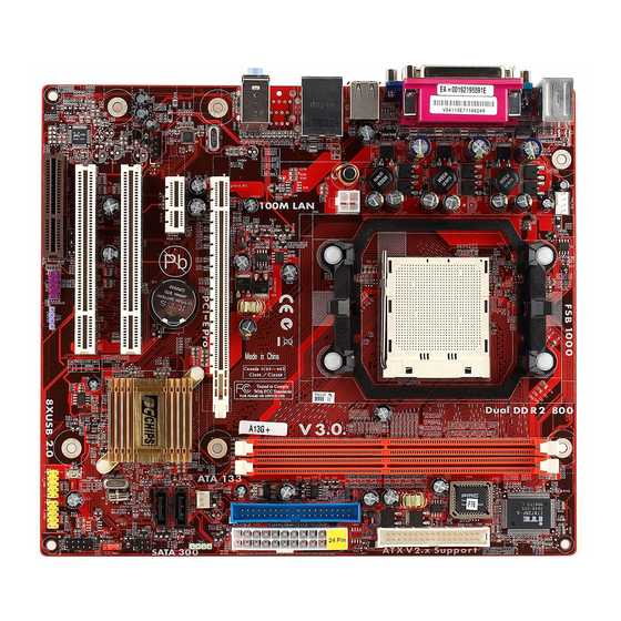
Page 9: Motherboard Components
Motherboard User’s Guide Motherboard Components ITEM LABEL COMPONENTS CPU_FAN CPU cooling fan connector CPU Socket Socket AM2 for AMD Athlon 64 FX/Athlon 64 X2 Dual-Core/Athlon 64 /Sempron processor DDRΙΙ1~2 240-pin DDR2 SDRAM slots Floppy Disk Drive connector PWR1 Standard 24-Pin AT X Power connector IDE1 Primary IDE connector SYS_FAN... -
Page 10: I/O Ports
Chapter 2: Motherboard Installation I/O Ports The illustration below shows a side view of the built-in I/O ports on the motherboard. Use the upper PS/2 port to connect a PS/2 pointing PS/2 Mouse device. PS/2 Keyboard Use the low er PS/2 port to connect a PS/2 keyboard. -
Page 11: Cpu Installation Procedure
Motherboard User’s Guide CPU Installation Procedure Follow these instructions to install the CPU: Unhook the locking lever of the CPU socket. Pull the locking lever away from the socket and raising it to the upright position. Match the pin1 corner marked as the beveled edge on the CPU with the pin1 corner on the socket. - Page 12 Chapter 2: Motherboard Installation Over its predecessor, DDR2-SDRAM offers greater bandwidth and density in a smaller package along with a reduction in power consumption. In addition, DDR2- SDRAM offers new features and functions that enable a higher clock rate and data rate operations of 800/667/533/400 MHz.
-
Page 13: Jumper Settings
Motherboard User’s Guide Note for dual-channel DDR: 1. You CAN NOT use only one DIMM2 for it might cause the system shutdown. 2. You need to use DIMM1 and DIMM2 with the same size of memory modules. Jumper Settings Connecting two pins with a jumper cap is SHORT; removing a jumper cap from these pins, OPEN. -
Page 14: Install The Motherboard
Chapter 2: Motherboard Installation Install The Motherboard Install the motherboard in a system chassis (case). The board is an micro-ATX size motherboard. You can install this motherboard in an ATX case. Make sure your case has an I/O cover plate matching the ports on this motherboard. Install the motherboard in a case. -
Page 15: Connecting Optional Devices
Motherboard User’s Guide Signal Signal HD_LED_P(+) FP PWR/SLP(+) HD_LED_N(-) FP PWR/SLP(-) RESET_SW_N(-) POWER_SW_P(+) RESET_SW_P(+) POWER_SW_N(-) RSVD_DNU 10 KEY Connecting Optional Devices Refer to the following for information on connecting the motherboard’s optional devices: SPK1: Speaker Header Connect the cable from the PC speaker to the SPK1 header on the motherboard. Signal SPKR F_AUDIO: Front Panel Audio Header... - Page 16 Chapter 2: Motherboard Installation F_USB1/2: Front Panel USB Headers The motherboard has USB ports installed on the rear edge I/O port array. Additionally, some computer cases have USB ports at the front of the case. If you have this kind of case, use auxiliary USB headers F_USB1/2 to connect the front-mounted ports to the motherboard.
-
Page 17: Install Other Devices
Motherboard User’s Guide Install Other Devices Install and connect any other devices in the system following the steps below. Floppy Disk Drive The motherboard ships with a floppy disk drive cable that can support one or two drives. Drives can be 3.5" or 5.25" wide, with capacities of 360K, 720K, 1.2MB, 1.44MB, or 2.88MB. - Page 18 Chapter 2: Motherboard Installation Serial ATA Devices The Serial ATA (Advanced Technology Attachment) is the standard interface for the IDE hard drives, which is designed to overcome the design limitations while enabling the storage interface to scale with the growing media rate demands of PC platforms.
-
Page 19: Expansion Slots
Motherboard User’s Guide Here is a list of CD_IN pin assignments. Signal CD IN L CD IN R Expansion Slots This motherboard has one PCI Ex16, one PCI Ex1 slots, two 32-bit PCI slots and one optional CNR slot. -
Page 20: Pci Slots
Chapter 2: Motherboard Installation Follow the steps below to install an PCI Express Pro/ PCI Express x1/Azalia CNR/PCI expansion card. 1. Locate the PCI Express Pro, PCI Express x1,Azalia CNR and PCI slots on the mainboard. 2. Remove the blanking plate of the slot from the system chassis. 3. - Page 21 Motherboard User’s Guide Table A: Supported PCI-E 8X VGA Cards List VGA Chip Model Name ASUS EAX300LE A334C/TD ASUS EAX1600XT SILENT/TVD/256M/A ASUS EAX1300PRO/TD/256M/A ASUS EAX850XTP/2DHTV/256M/A ASUS EAX1800XT2DHTV/512M/A ATI RADEON X850 CrossFire Edition 256M Colorful ATI X300/TV Out 128M Colorful X800XL/CH 128MB DDR Colorful X1300-GD3 /128M/128bit/DDR3 Colorful X1300-GD2 UP 256M/128bit/DDR2 Colorful X1600PRO-GD3/128M/128bit/DDR3...
- Page 22 Colorful 7800GT/CH 512MB DDRIII ECS N6200LE-128TT DDR1 128M ECS N6200LE-128TY/128M/64bit/DDR2 ECS N6600LE-128DV DDR1 128M ECS N6600LE-256DY DDR2 256M ECS N7300LE -256DZ DDR2 256M ECS N7300LE-128TY DDR2 128M ELSA PCX935 ELSA GLADIAC 760GT 256B3 2DT FORSA 7900GT 256MB DDRIII Dual DVI/HDTV...
-
Page 23: Chapter 3 Bios Setup Utility
Motherboard User’s Guide Chapter 3 BIOS Setup Utility Introduction The BIOS Setup Utility records settings and information of your computer, such as date and time, the type of hardware installed, and various configuration settings. Your computer applies the information to initialize all the components when booting up and basic functions of coordination between system compo- nents. -
Page 24: Standard Cmos Setup Page
Chapter 3: BIOS Setup Utility Some options on the main menu page lead to tables of items with installed values that you can use cursor arrow keys to highlight one item, and press PgUp and PgDn keys to cycle through alternative values of that item. The other options on the main menu page lead to dialog boxes requiring your answer OK or Cancel by selecting the [OK] or [Cancel] key. -
Page 25: Advanced Bios Features Page
Motherboard User’s Guide Video This item defines the video mode of the system. The motherboard has a built-in VGA graphics system; you must leave this item at the default value. Halt On Setting This item defines the operation of the system POST (Power On Self Test) routine. - Page 26 Chapter 3: BIOS Setup Utility Phonex-AwardBIOS CMOS Setup Utility CPU Feature Help Item NPT Fid Control [Auto] Use < > or < > to select a device, NPT Vid Control [Auto] then press <+> to move it up, or <- >...
- Page 27 Motherboard User’s Guide Hard Disk Boot Priority (Press Enter) Scroll to this item and press <Enter> to view the following screen: Phonex-AwardBIOS CMOS Setup Utility Hard Disk Boot Priority Help Item 1. Ch2 M : WDCWD1600JS-22MHB0 Use < > or < >...
- Page 28 Chapter 3: BIOS Setup Utility CPU Internal Cache (Enabled) All processors that can be installed in this motherboard use internal level 1 (L1) cache memory to improve performance. Leave this item at the default value for better performance. External Cache (Enabled) Most processors that can be installed in this system use external level 2 (L2) cache memory to improve performance.
- Page 29 Motherboard User’s Guide Boot Up NumLock Status (On) This item defines if the keyboard Num Lock key is active when your system is started. Gate A20 Option (Fast) This item defines how the system handles legacy software that was written for an earlier generation of processors.
-
Page 30: Advanced Chipset Features Page
Chapter 3: BIOS Setup Utility Advanced Chipset Features Page These items define critical timing parameters of the motherboard. You should leave the items on this page at their default values unless you are very familiar with the technical specifications of your system hardware. If you change the values incorrectly, you may introduce fatal errors or recurring instability into your system. - Page 31 Motherboard User’s Guide Phonex-AwardBIOS CMOS Setup Utility DRAM Configuration Onboard GPU [Enable If No Ext GPU] Frame Buffer Size [64M] Help Item GPU Bank Flip [Disabled] [Disabled] CPU Frequency [200.0] Menu Level K8<->NB HT Speed [Auto] K8<->NB HT Width [Auto] DRAM Configuration [Press Enter] PCIE Spread Spectrum...
- Page 32 Chapter 3: BIOS Setup Utility PCIE Spread Spectrum This item, when enabled, can significantly reduce the EMI (Electromagnetic Inter- ference) generated by the PCIE. SATA Spread Spectrum This item, when enabled, can significantly reduce the EMI (Electromagnetic Inter- ference) generated by the SATA. HT Spread Spectrum This item, when enabled, can significantly reduce the EMI (Electromagnetic Inter- ference) generated by the HT.
-
Page 33: Integrated Peripherals Page
Motherboard User’s Guide Integrated Peripherals Page These options display items that define the operation of peripheral components on the system’s input/output ports. Phonex-AwardBIOS CMOS Setup Utility Integrated Peripherals Help Item IDE Function Setup [Press Enter] RAID Config [Press Enter] Onboard Device Setup [Press Enter] Menu Level Super IO Device... -
Page 34: Ide Prefetch Mode
Chapter 3: BIOS Setup Utility Primary/Secondary Master/Slave UDMA Each IDE channel supports a master device and a slave device. This motherboard supports UltraDMA technology, which provides faster access to IDE devices. If you install a device that supports UltraDMA, change the appropriate item on this list to Auto. -
Page 35: Onchip Usb
Motherboard User’s Guide Onboard Device Setup (Press Enter) Scroll to this item and press <Enter> to view the following screen: Phonex-AwardBIOS CMOS Setup Utility Onboard Device Setup Onchip USB [V1.1 + V2.0] Help Item USB Memory Type [SHADOW] USB Keyboard Support [Enabled] USB Mouse Support [Enabled]... -
Page 36: Onboard Fdc Controller
Chapter 3: BIOS Setup Utility SuperIO Device (Press Enter) Scroll to this item and press <Enter> to view the following screen: Phonex-AwardBIOS CMOS Setup Utility SuperIO Device Onboard FDC Controller [Enabled] Onboard Serial Port 1 [3F8/IRQ4] Help Item Onboard Serial Port 2 [2F8/IRQ3] UART Mode Select [Normal]... -
Page 37: Power Management Setup Page
Motherboard User’s Guide Power Management Setup Page Power Management Setup Page Power Management Setup Page Power Management Setup Page Power Management Setup Page This option lets you control system power management. The system has various power-saving modes including powering down the hard disk, turning off the video, suspending to RAM, and software power down that allows the system to be automatically resumed by certain events. - Page 38 Chapter 3: BIOS Setup Utility Delay 4 Sec. then you have to hold the power button down for four seconds to cause a software power down. HPET Support This item enables or disables HPET support. Resume by PCI-E PME This system can be turned off with a software command. If you enable this item, the system can automatically resume if there is an incoming call on the PCI Express card.
-
Page 39: Init Display First
Motherboard User’s Guide PnP/PCI Configurations Page These options configure how PnP (Plug and Play) and PCI expansion cards operate in your system. Both the the ISA and PCI buses on the motherboard use system IRQs (Interrup ReQuests) and DMAs (Direct Memory Access). You must set up the IRQ and DMA assignments correctly through the PnP/PCI Configurations Setup utility for the motherboard to work properly. -
Page 40: Pc Health Status Page
Chapter 3: BIOS Setup Utility PC Health Status Page On motherboards that support hardware monitoring, this item lets you monitor the parameters for critical voltages, temperatures and fan speeds Phonex-AwardBIOS CMOS Setup Utility PC Health Status Smart Fan Function [Press Enter] Help Item Shutdown Temperature [Disabled]... - Page 41 Motherboard User’s Guide Shutdown Temperature Enables you to set the maximum temperature the system can reach before powering down. Warning Temperature Enables you to set the warning temperature before powering down. System Component Characteristics These fields provide you with information about the systems current operating status.
-
Page 42: Load Fail-Safe Defaults
Chapter 3: BIOS Setup Utility Load Fail-Safe Defaults This option opens a dialog box that lets you install fail-safe defaults for all appro- priate items in the Setup Utility: Press <Y> and then <Enter> to install the defaults. Press <N> and then <Enter> to not install the defaults. -
Page 43: Save & Exit Setup
Motherboard User’s Guide Save & Exit Setup Highlight this item and press <Enter> to save the changes that you have made in the Setup Utility and exit the Setup Utility. When the Save and Exit dialog box appears, press <Y> to save and exit, or press <N> to return to the main menu. Exit Without Saving Highlight this item and press <Enter>... -
Page 44: Chapter 4 Software & Applications
Chapter 4: Software & Applications Chapter 4 Software & Applications Introduction This chapter describes the contents of the support CD-ROM that comes with the motherboard package. The support CD-ROM contains all useful software, necessary drivers and utility programs to properly run our products. More program information is available in a README file, located in the same directory as the software. - Page 45 Motherboard User’s Guide The Browse CD button is a standard Windows command that you can check the contents of the disc with the Windows 98 file browsing interface. The Exit button closes the Auto Setup window. To run the program again, reinsert the CD-ROM disc in the drive;...
-
Page 46: Bundled Software Installation
Chapter 4: Software & Applications Note: To install the CNR card driver, please select the “Modem” item manually after the Auto Setup. Click on “Next >” and the CNR card driver will be installed automatically. The support software will automatically install. Once any of the installation procedures start, software is automatically installed in sequence. - Page 47 Motherboard User’s Guide...
Need help?
Do you have a question about the A13G Series and is the answer not in the manual?
Questions and answers