Table of Contents
Advertisement
Quick Links
Advertisement
Table of Contents

Related Manuals for Fagor DEN 8000


Summary of Contents for Fagor DEN 8000
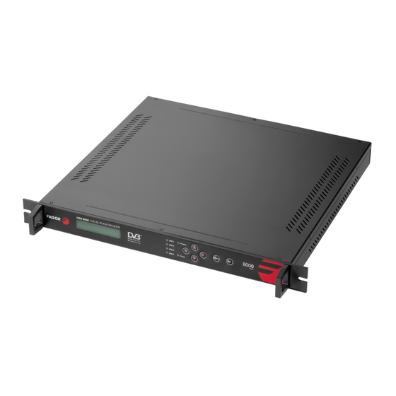
- Page 1 DEN 8000 Encoder 4xA/V...
-
Page 2: Table Of Contents
TABLE OF CONTENTS 1.- SAFETY INSTRUCTIONS 2.- SYSTEM PRINCIPLE 2.1 SYSTEM DIAGRAM 2.2 WORKING PRINCIPLE 2.2.1 VIDEO AUDIO A/D PROCESS 2.2.2 A/V ENCODING 2.2.3 AV TS PROCESS 2.2.4 DATA OUTPUT PORT 3.- SPECIFICATIONS 4.- EQUIPMENT CONNECTION 4.1 FRONT PANEL DISPLAY & KEY BUTTON 4.2 REAR PANEL 5. -
Page 3: Safety Instructions
1. SAFETY INSTRUCTION ● Read this manual carefully before use. ● Do not open the case without disconnecting it from the mains ● Allows the air circulation around the equipment ● Protects against the water or liquids drops on the equipment ●... -
Page 4: Working Principle
2.2. WORKING PRINCIPLE The DEN 8000 encoder structure is as per above picture, which consists of AV A/C process unit, AV encoding unit, TS process unit, data output unit and CPU. 2.2.1 VIDEO AUDIO A/D PROCESS AV A/D process unit converts analog audio & video input into digital format and send it to encoding chipset. - Page 5 > Programming via front panel (keyboard + LCD display) or PC (local or remote). > Mountable in 19” rack. > Includes: - 4 x 3RCA-3BNC cables for 4 analogue A/V sources. - 1 x BNC-F(m) cable for one COFDM output. - 1 x user's manual.
-
Page 6: Equipment Connection
4. EQUIPMENT CONNECTION 4.1. FRONT PANEL DISPLAY AND KEY BUTTON Error indicator POWER indicator Directional arrow key Enter Exit ENC 1~ENC4 Encoder Indicator LEFT, RIGHT:move the cursors UP, DOWN:change parameters ENTER:confirm and operate Exit:back to upper menu or cancel the setting Note :... -
Page 7: Rear Panel
4.2. REAR PANEL 1 CH1 A/V input 2 CH2 A/V input 3 CH3 A/V input 4 CH4 A/V input 5 ASI port (optional )/IP out( optional) 6 ASI output port 1 7 ASI output port 2 8 Ethernet port 9 Power switch... -
Page 8: Operation
If one of the inputs is not used, this input could be removed from the output MUX Entering in: Encoder x > Multiplexing > YES/NO: Section 5.2.3 5.2. MENU OPTION 5.2.1. LOCK STATUS DISPLAY DEN 8000 4IN 1 Encoder PG:04 BR:00.000Mbps 5.2.2. MAIN MENU DISPLAY 1. Encoder 1 2. Encoder 2 3. - Page 9 5.2.4. VIDEO SETTING: Select video config, LCD display as below : 1.2.1 Video Enable 1.2.2 Video mode 1.2.3 GOP 1.2.4 Brightness 1.2.5 Contrast 1.2.6 Saturation 1.2.7 Hue 1.2.8 Compression 5.2.4.1. VIDEO ENABLE. The user can switch ON/OFF the video at the output 1.1.1VIDEO ENABLE 1 On...
- Page 10 5.2.4.7. HUE: The color hue is adjusted 1.1.7 Color +000 5.2.4.8. VIDEO COMPRESSION: The user can select one of them 1.1.8 Video compression 3/4D1 2/3D1 5.2.5. AUDIO SETTING : The following parameters can be settled 1.2.1Coding Type 1.2.2Samping Freq. 1.2.3Output bit rate 1.2.4Audio mode 5.2.5.1.
- Page 11 5.2.5.4. AUDIO MODE: There are the following options 1.2.4 Audio mode Stereo Joined Stereo Dual Single Channel Single 5.2.6. SYSTEM SETTING: The programmable parameters are 2.4.1 Encoding bitrate 2.4.2 Bitrate mode 2.4.3 Program provider 2.4.4 Program name 2.4.5 Program number 2.4.6 PMT PID 2.4.7 VIDEO PID 2.4.8 AUDIO PID...
- Page 12 5.2.6.5. PROGRAM NUMBER: The user can set the program number 2.4.5 Progr number 0001 5.2.6.6. PMT PID: The user can set the PMT and PID 2.4.6PMT PID 0256 5.2.6.7. VIDEO PID: The user can set the video PID number 2.4.7VIDEO PID 0257 5.2.6.8.
- Page 13 5.2.7.2. TS ID: The user can set the TS ID 5.2 TS ID 00000 5.2.8. NETWORK SETTING : The user can define the following Network parameters for Ethernet local or remote access 6.1 IP address 192.168.000.131 6.2 Sub net mask 255.255.255.000 6.3 gateway 192.168.000.001...
-
Page 14: Version
5.2.11. VERSION: The Software and Hardware version are displayed 9. Version SW:1.14 HW:1.03 5.2.12. LANGUAGE: The display language is English 10 Languages English 5.2.13. ERROR MESSAGES: The display shows the systems errors 11 Error info 04: ASI Unlocked 6. SYSTEM FAILURE OR TROUBLE SHOOTING 6.1. -
Page 15: Ce Marking
7.- CE MARKING... - Page 16 Fagor Electrónica, S.Coop. San Andrés, s/n E-20500 Mondragón (Spain) Tel: + 34 943 71 25 26 Fax: + 34 943 71 28 93 www.fagorelectronica.com...
Need help?
Do you have a question about the DEN 8000 and is the answer not in the manual?
Questions and answers