
Related Manuals for SMA Sunny Boy SB 1100LV


Summary of Contents for SMA Sunny Boy SB 1100LV
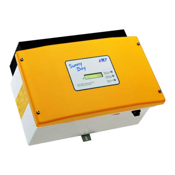
- Page 1 Sunny Boy SB 1100LV Inverter for Photovoltaic Plants Installation Guide Version 1.1 SB1100LV-11:SE2006 IME-SB1100LV...
-
Page 3: Table Of Contents
Technologie AG Table of Contents Inhaltsverzeichnis Explanation of the symbols used: ... . 5 Foreword ....... 7 Target group . - Page 4 CE declaration of conformity ....45 SMA grid guard certificate ....46 Replacing the varistors.
-
Page 5: Explanation Of The Symbols Used
Technologie AG Explanation of the symbols used: 1 Explanation of the symbols used: To ensure optimum use of these instructions, please note the following explanation of symbols used. This symbol identifies an example. This symbol identifies a notice where failure to follow the advice will make the procedure or operation more difficult. - Page 6 Explanation of the symbols used: Technologie AG Page 6 SB1100LV-11:SE2006 Installation Guide...
-
Page 7: Foreword
Foreword 2 Foreword The Sunny Boy SB 1100LV contains the SMA grid guard 2. This is a type of independent disconnection device. It ensures that the Sunny Boy SB 1100LV complies with the VDEW (Verband der Elektrizitätswirtschaft – German Electricity... - Page 8 Foreword Technologie AG Page 8 SB1100LV-11:SE2006 Installation Guide...
-
Page 9: Safety Instructions
You must also make sure that no voltage is present in the device. Caution! Electrostatic charge! When working on the Sunny Boy SB 1100LV and handling the components, remember to observe all ESD safety regulations. Electronic components are susceptible to electrostatic charge. Discharge any electrostatic charge by touching the grounded enclosure before handling any electronic component. - Page 10 Safety instructions Technologie AG Page 10 SB1100LV-11:SE2006 Installation Guide...
-
Page 11: Overview
Technologie AG Overview 4 Overview 4.1 Unit description The following diagram gives a schematic overview of the various components and connection points inside the Sunny Boy SB 1100LV with the cover removed: Socket communication Varistors, (RS232, RS485, NLM Piggy- page 47... -
Page 12: External Dimensions
Overview Technologie AG 4.2 External dimensions 214 mm 434 mm 295 mm Page 12 SB1100LV-11:SE2006 Installation Guide... -
Page 13: Installation Requirements
The ambient temperature must not be outside the -25 °C to +60 °C range. The Sunny Boy SB 1100LV should be installed in a place where it is not exposed to direct sunlight. An increased ambient temperature can reduce the yield of the PV system. - Page 14 When choosing the installation site, ensure there is enough space for heat to dissipate. Under normal conditions, the following guidelines should be applied for the space to be kept clear around the Sunny Boy SB 1100LV: Minimum clearance Sides...
-
Page 15: Pv Generator Requirements
Installation requirements 5.2 PV generator requirements The Sunny Boy SB 1100LV is internally designed to be connected directly to up to two strings (PV modules wired in series) having a homogenous structure (modules of the same type, identical orientation and tilt). - Page 16 Installation requirements Technologie AG Attention! We recommend using a 16 A line circuit breaker to protect the power circuit. No loads should be connected to this power circuit. Rating for a line circuit breaker in a photovoltaic electrical power unit operated in parallel with the low-voltage grid Various factors should be taken into account when selecting line circuit breakers.
- Page 17 Technologie AG Installation requirements AC cable system impedance should not exceed 1 ohm. This is necessary, amongst other things, for the correct operation of impedance observation. In addition, we recommend dimensioning the conductor cross-section so that line losses do not exceed 1% at the nominal power.
- Page 18 Installation requirements Technologie AG The Sunny Boy SB 1100LV is designed for operation on 220 - 240 V grids with a grid frequency of 50 Hz. When connecting an inverter to the public grid, please adhere to the local connection requirements of your grid operator.
-
Page 19: Installation
Fit the wall bracket (1). To mark the positions to drill the holes, you can use the wall bracket as a drilling template. Now hook the Sunny Boy SB 1100LV onto the wall bracket (2) at its upper mounting plate so that it cannot be moved sideways. -
Page 20: Electrical Installation
Installation Technologie AG 6.2 Electrical installation Attention! Make sure to check the polarity of the strings before connecting them! The complete wiring for a Sunny Boy SB 1100LV is shown schematically in the following diagram: Circuit max. 2.5 mm² Communication... -
Page 21: Connecting The Ac Output
Technologie AG Installation 6.2.1 Connecting the AC output Warning! Voltage! Before you connect the mains cable to the AC connection socket, make sure that no voltage is present in the cable. A round plug connector system is used, which allows various cable diameters to be used in the cable outlet. - Page 22 Installation Technologie AG Connecting the AC output with PG13.5 To connect a cable with a maximum cross-section of 13.5 mm², proceed as follows. Press the sealing ring into the cord grip. Sealing ring Cord grip Now slide the pressure screw over the cable first of all, followed by the cord grip with the sealing ring in it.
- Page 23 Attention! Do not switch the line circuit breaker on yet! The Sunny Boy SB 1100LV may only be connected to the AC grid once the PV strings are connected and the device is securely closed.
- Page 24 Installation Technologie AG Connecting the AC plug with PG16 To connect a cable with a cross-section between 13.5 mm² and 16 mm², proceed as follows. First of all, slide the pressure screw with the PG16 screw fitting onto the cable. Now slide the threaded sleeve over the cable.
- Page 25 Attention! Do not switch the line circuit breaker on yet! The Sunny Boy SB 1100LV may only be connected to the AC grid once the PV strings are connected and the device is securely closed.
-
Page 26: Pv String (Dc) Connection
Attention! Do not connect strings to the Sunny Boy SB 1100LV that contain a ground fault until you have fixed the earth fault in the PV generator. Repeat points 2 and 3 for each string. -
Page 27: Reverse Current
Advice on generator configuration for PV systems using the Sunny Boy SB 1100LV The Sunny Boy SB 1100LV operates with very high input currents. This does not sound particularly spectacular but it has practical consequences because, in such large generators, certain faults which are totally uncritical in string systems must be allowed for. - Page 28 Installation Technologie AG causes reverse current to flow through the faulty generator string that, depending on the amount of current, may lead to excessive heating or destruction of the modules in this string. Among other symptoms, the following faults may lead to reduction of the open circuit terminal voltage of a generator string and subsequent reverse current in parallel- connected systems: •...
- Page 29 Technologie AG Installation How to avoid reverse current in the modules? First, we must know that today's state-of-the-art bypass diodes for module construction do not affect reverse current in the module, but only reduce the effects of any shading which may occur. The following standard methods of preventing or reducing reverse current to the modules exist.
-
Page 30: Commissioning
Are the plug connectors of the modules and the inverters suited for this reverse current? Is the string wiring suited for this reverse current? 6.4 Commissioning You can start up the Sunny Boy SB 1100LV when • the lid is securely screwed shut, •... - Page 31 If despite checking the string voltages the LED signal occurs again when the PV generator is connected to the Sunny Boy SB 1100LV, disconnect the PV generator from the Sunny Boy again and contact SMA Technologie AG (see chapter 13 "Contact"...
- Page 32 Installation Technologie AG Page 32 SB1100LV-11:SE2006 Installation Guide...
-
Page 33: Opening And Closing The Sunny Boy
1100LV by tightening the four screws evenly. Switch the DC circuit breaker to the "on" position. Switch the line circuit breaker to the "on" position. Now check whether the LED display on the Sunny Boy SB 1100LV indicates that the device is functioning correctly. Installation Guide... - Page 34 Opening and closing the Sunny Boy Technologie AG Page 34 SB1100LV-11:SE2006 Installation Guide...
-
Page 35: Technical Data
Technologie AG Technical data 8 Technical data 8.1 PV generator connection data Description Unit Setting Max. input open circuit voltage 60 V PV 0 (based on -10°C cell temperature) Input voltage, MPP range 21 V ... 60 V Max. input current 62 A PV max Max. -
Page 36: Grid Connection Data
Germany: 198 ... 253 / 260 V AC Operating range, grid frequency 45.5 ... 54.5 Hz Germany: 47.55 ... 50.2 Hz All-pole isolator grid side Independent disconnection device ("SMA grid guard 2"), double implementation Phase shift angle (based on the cos phi current's fundamental frequency) Overvoltage category Test voltage (DC) 1.6 kV (1 s routine testing / 5 s type... -
Page 37: Device Description
92 % ηeuro European standard efficiency 90.4 % The efficiency of the Sunny Boy SB 1100LV depends mainly on the input voltage of the connected PV strings. The lower the input voltage, the higher the efficiency. Output power [W] Installation Guide... -
Page 38: Operating Parameters
Technical data Technologie AG 8.4 Operating parameters Warning! Unauthorised changes to the operating parameters may result in: • injury or accidents as a result of changing the internal safety routines in the Sunny Boy, • voiding the Sunny Boy's operating approval certificate, •... - Page 39 AC side) or in "Stopp" mode. Inst.-Code Parameters for self contained power system recognition can only be changed after entering the "SMA grid guard" password. LDVtgC Compensation for the voltage drop in the cabling. With this parameter, the voltage drop between the inverter and the grid connection point is taken into account.
- Page 40 Turbine Mode: Operating mode for wind energy systems. Off Grid: Operating mode for Sunny Boys in a stand-alone grid. Plimit Upper limit for AC output power SMA-SN Serial number of the Sunny Boy Software-BFR Firmware version of the operation control unit (BFR)
-
Page 41: Parameter Settings For Germany
Technologie AG Technical data 8.4.2 Parameter settings for Germany Grayed out parameters are only displayed in installer mode. The table below contains the parameters that are applicable in Germany. Name Unit Value range Factory setting ACVtgRPro 230 ... 300 AntiIsland-Ampl * grd 0 ... -
Page 42: Country-Specific Parameter Settings
Technologie AG Parameters designated with * are safety-related grid monitoring parameters. To change the SMA grid guard parameters, you must enter you personal SMA grid guard password (Inst.-Code). Please call the Sunny Boy Hotline to obtain your personal SMA grid guard password. -
Page 43: Non-Modifiable Parameters
8.4.4 Non-modifiable parameters Grayed out parameters are only displayed in installer mode. The following parameters are displayed in the parameter list but cannot be changed: Name Unit Factory setting Fac-Pderating Fac-Tavg Plimit 1100 SMA-SN Software-BFR Software-SRR Uac-Tavg Installation Guide SB1100LV-11:SE2006 Page 43... - Page 44 Technical data Technologie AG Page 44 SB1100LV-11:SE2006 Installation Guide...
-
Page 45: Certificates
We declare that the above specified devices are compliant with the regulations of the European Community, in terms of the design and the version fabricated by SMA. This especially applies for the EMC Regulation defined in 89/336/EWG and the LV- regulation defined in 73/23/EWG. -
Page 46: Sma Grid Guard Certificate
Certificates Technologie AG 9.2 SMA grid guard certificate The Sunny Boy SB 1100LV is equipped with the "SMA grid guard 2“ independent disconnection device and it is covered by the industrial trade association "SMA grid guard 2“ certificate. Page 46... -
Page 47: Replacing The Varistors
Replacing the varistors 10 Replacing the varistors The Sunny Boy SB 1100LV is a complex high-technology device. As a result, the possibilities for fixing faults on site are limited to just a few items. Please don't try to carry out repairs other than those described here. Use the SMA Technologie AG 24-hour exchange service and repair service instead. - Page 48 2 and 3. If there is not, then that varistor is not working. The positions of the varistors in the Sunny Boy SB 1100LV can be seen in the diagram in chapter 4.1 "Unit description" (Page 11).
- Page 49 Sunny Boy SB 1100LV indicates that the device is functioning correctly. If no ground fault and no defective varistor were found, there is probably a fault in the Sunny Boy. In this case, contact the SMA hotline to discuss what to do next. Installation Guide SB1100LV-11:SE2006...
- Page 50 Replacing the varistors Technologie AG Page 50 SB1100LV-11:SE2006 Installation Guide...
-
Page 51: Rating For A Line Circuit Breaker
Example for the thermal rating for a line circuit breaker in a photovoltaic electrical power unit operated in parallel with the low-voltage grid. We assume a PV system with 9 Sunny Boy SB 1100LV inverters, with three inverters per phase. - Page 52 Rating for a line circuit breaker Technologie AG When selecting line circuit breakers, a number of load factors need to be taken into account. These can be found in the respective data sheets. Example for the thermal selection of a 10 A line circuit breaker with B sensitivity with no gap between the circuit breakers: For example, one manufacturer's circuit breaker may be designed for an ambient temperature of 50 °C.
- Page 53 Technologie AG Rating for a line circuit breaker Summary: The selected line circuit breaker can be used in our example case since the maximum current-carrying capacity for fault-free operation is higher than the maximum output current of the inverter used. It will not trigger under rated operating conditions! If the calculated current-carrying capacity of the circuit breaker had been lower than the maximum output current from the inverter, the following solution might have been used:...
- Page 54 Rating for a line circuit breaker Technologie AG Page 54 SB1100LV-11:SE2006 Installation Guide...
-
Page 55: The Communications Interface
Installation or replacement of the communications interface is only to be carried out by a trained electrician. The communications interface is used to communicate with SMA communication devices (e. g. Sunny Boy Control, Sunny WebBox) or a PC with appropriate software (e. -
Page 56: Connection Of The Interface
The communications interface Technologie AG 12.1 Connection of the interface Attention! When opening the Sunny Boy, follow all the safety instructions as described in section 3. Electrostatic discharges are an acute danger to the Sunny Boy and to the communications interface. Ground yourself by touching PE before removing the communications interface from the packaging, and before touching any components within the Sunny Boy. -
Page 57: Jumper Functions
Technologie AG The communications interface Enclosure feed-throughs in the base of the Sunny Boy Cable route (gray surface) PE connector Screw terminals for connection of the communication wires Jumper slot Interface port 12.1.1 Jumper functions Jumper A Jumper B Jumper C RS232 RS485 Termination... - Page 58 The communications interface Technologie AG Page 58 SB1100LV-11:SE2006 Installation Guide...
-
Page 59: Contact
Technologie AG Contact 13 Contact If you have any questions or technical problems concerning the Sunny Boy SB 1100LV, please contact our hotline. Have the following information available when you contact SMA: • Inverter type • Type and number of modules connected •... - Page 60 The information contained in this document is the property of SMA Technologie AG. Publishing its content, either partially or in full, requires the written permision of SMA Technologie AG. Any internal company copying of the document for the purposes of evaluating the product or its correct implementation is allowed and does not require permission.
- Page 62 Sales Solar Technology www.SMA.de SMA Technologie AG Hannoversche Strasse 1–5 34266 Niestetal, Germany Tel. : +49 561 9522 4000 Fax: +49 561 9522 4040 E-Mail: Info@SMA.de Freecall: +800 SUNNYBOY Freecall: +800 7 8 6 6 9 2 6 9 Innovation in Systems Technology...
Need help?
Do you have a question about the Sunny Boy SB 1100LV and is the answer not in the manual?
Questions and answers