Cisco Catalyst 1000 Series Hardware Installation Manual
24-port and 48-port switch
Hide thumbs
Also See for Catalyst 1000 Series:
- Hardware options & upgrade manual (142 pages) ,
- Hardware installation manual (96 pages) ,
- Manual (20 pages)
Table of Contents
Advertisement
Advertisement
Table of Contents

Related Manuals for Cisco Catalyst 1000 Series


Summary of Contents for Cisco Catalyst 1000 Series
- Page 1 Cisco Catalyst 1000 Series 24-Port and 48-Port Switch Hardware Installation Guide First Published: 2019-12-25 Americas Headquarters Cisco Systems, Inc. 170 West Tasman Drive San Jose, CA 95134-1706 http://www.cisco.com Tel: 408 526-4000 800 553-NETS (6387) Fax: 408 527-0883...
-
Page 2: Table Of Contents
Port LEDs Rear Panel Internal Power Supply Security Slot Network Configurations C H A P T E R 2 Switch Installation Safety Warnings Box Contents Tools and Equipment Installation Guidelines Cisco Catalyst 1000 Series 24-Port and 48-Port Switch Hardware Installation Guide... - Page 3 System LEDs Switch Connections Bad or Damaged Cable Ethernet and Fiber-Optic Cables Link Status 10/100/1000 Port Connections 10/100/1000 PoE+ Port Connections SFP and SFP+ Module Interface Settings Ping End Device Cisco Catalyst 1000 Series 24-Port and 48-Port Switch Hardware Installation Guide...
- Page 4 Installing the Cisco Microsoft Windows USB Device Driver Installing the Cisco Microsoft Windows XP USB Driver Installing the Cisco Microsoft Windows 2000 USB Driver Installing the Cisco Microsoft Windows 7 USB Driver Cisco Catalyst 1000 Series 24-Port and 48-Port Switch Hardware Installation Guide...
- Page 5 Contents Uninstalling the Cisco Microsoft Windows USB Driver Uninstalling the Cisco Microsoft Windows XP and 2000 USB Driver Uninstalling the Cisco Microsoft Windows 7 USB Driver Cisco Catalyst 1000 Series 24-Port and 48-Port Switch Hardware Installation Guide...
- Page 6 Contents Cisco Catalyst 1000 Series 24-Port and 48-Port Switch Hardware Installation Guide...
-
Page 7: Preface
[x | y] Optional alternative keywords are grouped in brackets and separated by vertical bars. {x | y} Required alternative keywords are grouped in braces and separated by vertical bars. Cisco Catalyst 1000 Series 24-Port and 48-Port Switch Hardware Installation Guide... - Page 8 Use the statement number provided at the end of each warning to locate its translation in the translated safety warnings that accompanied this device. Statement 1071 SAVE THESE INSTRUCTIONS Cisco Catalyst 1000 Series 24-Port and 48-Port Switch Hardware Installation Guide viii...
-
Page 9: Obtaining Documentation And Submitting A Service Request
Obtaining Documentation and Submitting a Service Request For information on obtaining documentation, submitting a service request, and gathering additional information, see the monthly What's New in Cisco Product Documentation, which also lists all new and revised Cisco technical documentation, at: http://www.cisco.com/c/en/us/td/docs/general/whatsnew/whatsnew.html... - Page 10 Preface Obtaining Documentation and Submitting a Service Request Cisco Catalyst 1000 Series 24-Port and 48-Port Switch Hardware Installation Guide...
-
Page 11: Product Overview
C H A P T E R Product Overview The Cisco Catalyst 1000 Series switches are fixed-configuration, Gigabit Ethernet switches that provide entry-level enterprise-class Layer 2 access for branch offices, conventional workspace, and out-of-wiring closet applications. Cisco Catalyst 1000 Series switches provide support for the following features: •... -
Page 12: Front Panel
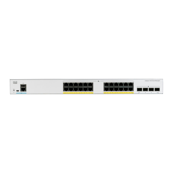
48 10/100/1000 PoE+ ports (PoE budget of 740W); four 10-Gigabit Ethernet SFP+ module uplink slots Front Panel This section describes the front panel components of a 24-port and 48-port Cisco Catalyst 1000 switch. • 24 or 48 downlink ports of one of these types: • 10/100/1000 Ethernet •... - Page 13 Product Overview Front Panel Figure 1: Front Panel of a 24-Port Cisco Catalyst 1000 PoE Switch USB Type A port RJ-45 console port Reset button 24 10/100/1000 PoE+ ports System LED SFP module slots USB mini-Type B (console) port Figure 2: Front Panel of a 48-Port Cisco Catalyst 1000 PoE Switch...
-
Page 14: Poe Ports
• USB mini-Type B console port (5-pin connector). If you use the USB mini-Type B console port, the Cisco Windows USB device driver must be installed on any PC connected to the console port (for operation with Microsoft Windows). Mac OS X or Linux do not require special drivers. -
Page 15: Usb Type A Port
The port supports Cisco USB flash drives with capacities from 128 MB to 8 GB (USB devices with port densities of 128 MB, 256 MB, 1 GB, 4 GB, and 8 GB are supported). Cisco IOS software provides standard file system access to the flash device: read, write, erase, and copy, as well as the ability to format the flash device with a FAT file system. -
Page 16: Leds
Software Configuration Guide. LEDs You can use the switch system and port LEDs to monitor switch activity and performance. Figure 4: System LED Cisco Catalyst 1000 Series 24-Port and 48-Port Switch Hardware Installation Guide... -
Page 17: System Led
Activity. Port is sending or receiving data. Rear Panel • A security slot • An AC power connector • A loop (for the optional power cord retainer) • Heat sink fins (fanless models only) Cisco Catalyst 1000 Series 24-Port and 48-Port Switch Hardware Installation Guide... -
Page 18: Internal Power Supply
All the switches are powered through their internal power supplies. The internal power supply is an autoranging unit that supports input voltages between 100 and 240 VAC (max of 90V to 264V). The AC frequency range Cisco Catalyst 1000 Series 24-Port and 48-Port Switch Hardware Installation Guide... -
Page 19: Security Slot
See the switch software configuration guide for network configuration concepts and examples of using the switch to create dedicated network segments and interconnecting the segments through Fast Ethernet and Gigabit Ethernet connections. Cisco Catalyst 1000 Series 24-Port and 48-Port Switch Hardware Installation Guide... - Page 20 Product Overview Network Configurations Cisco Catalyst 1000 Series 24-Port and 48-Port Switch Hardware Installation Guide...
-
Page 21: Switch Installation
Before working on equipment that is connected to power lines, remove jewelry (including rings, necklaces, and watches). Metal objects will heat up when connected to power and ground and can cause serious burns or weld the metal object to the terminals. Statement 43 Cisco Catalyst 1000 Series 24-Port and 48-Port Switch Hardware Installation Guide... -
Page 22: Safety Warnings
Do not work on the system or connect or disconnect cables during periods of lightning activity. Statement 1001 Warning Read the installation instructions before connecting the system to the power source. Statement 1004 Cisco Catalyst 1000 Series 24-Port and 48-Port Switch Hardware Installation Guide... - Page 23 Contact the appropriate electrical inspection authority or an electrician if you are uncertain that suitable grounding is available. Statement 1024 Warning Class 1 LED product. Statement 1027 Cisco Catalyst 1000 Series 24-Port and 48-Port Switch Hardware Installation Guide...
- Page 24 Use the statement number provided at the end of each warning to locate its translation in the translated safety warnings that accompanied this device. Statement 1071 Cisco Catalyst 1000 Series 24-Port and 48-Port Switch Hardware Installation Guide...
-
Page 25: Box Contents
To prevent airflow restriction, allow clearance around the ventilation openings to be at least: 3 inches (7.6 cm). Statement 1076 Warning Hot surface. Statement 1079 Box Contents This section lists the contents of the shipping box for a 24-port and 48-port Cisco Catalyst 1000 switch. Cisco Catalyst 1000 Series 24-Port and 48-Port Switch Hardware Installation Guide... -
Page 26: Tools And Equipment
Switch Installation Tools and Equipment Figure 8: Box Contents of a 24-Port and 48-Port Cisco Catalyst 1000 Switch 24-port and 48-port Cisco Catalyst 1000 Four Number-12 Phillips pan-head screws switch (48-0523-01) AC power cord Four Number-10 Phillips pan-head screws (48-0627-01) -
Page 27: Installation Guidelines
As the switch powers on, it begins the POST, a series of tests that runs automatically to ensure that the switch functions properly. LEDs can blink during the test. The SYST LED blinks green. Cisco Catalyst 1000 Series 24-Port and 48-Port Switch Hardware Installation Guide... -
Page 28: Installing The Switch
SYST LED turns amber. POST failures are usually fatal. Call Cisco technical support representative if your switch fails POST. After a successful POST, unplug the power cord from the switch and install the switch in a rack, on a wall, on a table, or on a shelf. -
Page 29: Attaching The Rack-Mount Brackets
24-inch brackets Attaching the Rack-Mount Brackets Attaching the Rack-Mount Brackets to a 24-Port and 48-Port Cisco Catalyst 1000 Switch Use two Phillips flat-head screws to attach the long side of the bracket to each side of the switch. Cisco Catalyst 1000 Series 24-Port and 48-Port Switch Hardware Installation Guide... - Page 30 Switch Installation Attaching the Rack-Mount Brackets Figure 10: Attaching 19-inch Brackets to a 24-Port and 48-Port Cisco Catalyst 1000 Switch Front-mounting position Mid-mounting position Cisco Catalyst 1000 Series 24-Port and 48-Port Switch Hardware Installation Guide...
-
Page 31: Mounting A 24-Port Or 48-Port Switch In A Rack
Use the four supplied Phillips machine screws to attach the brackets to the rack. Step 2 Use the black Phillips machine screw to attach the cable guide to the left or right bracket. Figure 11: Mounting the Switch in a Rack Cisco Catalyst 1000 Series 24-Port and 48-Port Switch Hardware Installation Guide... -
Page 32: Wall-Mounting
Attaching the Brackets for Wall-Mounting Procedure Step 1 Attach a 19-inch bracket to one side of the switch. Step 2 Follow the same steps to attach the second bracket to the opposite side. Cisco Catalyst 1000 Series 24-Port and 48-Port Switch Hardware Installation Guide... -
Page 33: Mounting On A Wall
Statement 378 Caution Following safety regulations, wall-mount the switch with its front panel facing down. Cisco Catalyst 1000 Series 24-Port and 48-Port Switch Hardware Installation Guide... -
Page 34: Installing The Switch On A Table Or Shelf
Installing the Switch on a Table or Shelf Procedure Step 1 To install the switch on a table or shelf, locate the adhesive strip with the rubber feet in the mounting-kit envelope. Cisco Catalyst 1000 Series 24-Port and 48-Port Switch Hardware Installation Guide... -
Page 35: After Switch Installation
Figure 14: Inserting the Retainer Through the Lanced Loop AC power cord Sleeve for thinner power cords Power cord retainer Loop Step 3 Slide the retainer through the first latch. Cisco Catalyst 1000 Series 24-Port and 48-Port Switch Hardware Installation Guide... - Page 36 Smaller sleeve for thin power cords Step 4 Slide the retainer through the other latches to lock it. Figure 16: Locking the Retainer AC power cord Latches Sleeve for thin power cords Cisco Catalyst 1000 Series 24-Port and 48-Port Switch Hardware Installation Guide...
-
Page 37: Installing Sfp Modules
Figure 18: Securing the Power Cord in the Retainer Installing SFP Modules See the switch release notes on Cisco.com for the list of supported SFP modules. Use only Cisco SFP modules on the switch. Each Cisco module has an internal serial EEPROM that is encoded with security information. - Page 38 If the module has a bale-clasp latch, close it. Step 6 For fiber-optic SFP or SFP+ modules, remove the dust plugs and save. Step 7 Connect the SFP cables. Cisco Catalyst 1000 Series 24-Port and 48-Port Switch Hardware Installation Guide...
-
Page 39: Removing An Sfp Or Sfp+ Module
Step 5 Grasp the SFP or SFP+ module, and carefully remove it from the module slot. Step 6 Place the module in an antistatic bag or other protective environment. Cisco Catalyst 1000 Series 24-Port and 48-Port Switch Hardware Installation Guide... -
Page 40: Connecting To Sfp Or Sfp+ Modules
Insert one end of the fiber-optic cable into the SFP or SFP+ module port. Step 3 Insert the other cable end into a fiber-optic receptacle on a target device. Cisco Catalyst 1000 Series 24-Port and 48-Port Switch Hardware Installation Guide... -
Page 41: Connecting To 1000Base-T Sfp
Cisco.com. Caution To prevent ESD damage, follow your normal board and component handling procedures. Cisco Catalyst 1000 Series 24-Port and 48-Port Switch Hardware Installation Guide... -
Page 42: 10/100/1000 Poe+ Port Connections
• Use the show hardware led port power privileged EXEC command to show the PoE status for all ports. • Use the show interfaces privileged EXEC command to see if the port is in error-disabled, disabled, or shutdown. Reenable the port if necessary. Cisco Catalyst 1000 Series 24-Port and 48-Port Switch Hardware Installation Guide... -
Page 43: 10/100/1000 Ethernet Port Connections
PoE power budget. • Verify the cable type. Many legacy powered devices, including older Cisco IP phones and access points that do not fully support IEEE 802.3af, might not support PoE when connected to the switch by a crossover cable. - Page 44 Straight-Through Cable Switch to router Switch to IP phone 100BASE-TX and 1000BASE-T traffic requires twisted four-pair, Category 5 or higher. 10BASE-T traffic can use Category 3 cable or higher. Cisco Catalyst 1000 Series 24-Port and 48-Port Switch Hardware Installation Guide...
-
Page 45: Troubleshooting
You can also get statistics from Device Manager, from the CLI, or from an SNMP workstation. Switch POST Results POST failures are usually fatal. Contact your Cisco technical support representative if your switch does not pass POST. System LEDs If you have physical access to the switch, look at the port LEDs for troubleshooting information about the switch. -
Page 46: Ethernet And Fiber-Optic Cables
• Use the show interfaces privileged EXEC command to see if the port is in error-disabled, disabled, or shutdown. Reenable the port if necessary. • Verify that the power supply installed in the switch meets the power requirements of your connected devices. Cisco Catalyst 1000 Series 24-Port and 48-Port Switch Hardware Installation Guide... -
Page 47: Sfp And Sfp+ Module
SFP and SFP+ Module Use only Cisco SFP or SFP+ modules in the switch. Each Cisco module has an internal serial EEPROM that is encoded with security information. This encoding provides a way for Cisco to identify and validate that the module meets the requirements for the switch. -
Page 48: Switch Performance
Finding the Switch Serial Number If you contact Cisco Technical Assistance, you need to know the switch serial number. You can also use the show version privileged EXEC command to see the switch serial number. - Page 49 Troubleshooting Finding the Switch Serial Number Figure 22: Serial Number Location on a 24-Port Cisco Catalyst 1000 Series Switches QR code 4 in 1 label (includes PID number, Serial number, MAC address, and CLEI code) Figure 23: Serial Number Location on a 48-Port Cisco Catalyst 1000 Series Switches...
- Page 50 Troubleshooting Finding the Switch Serial Number Serial number Product label MII label Cisco Catalyst 1000 Series 24-Port and 48-Port Switch Hardware Installation Guide...
-
Page 51: Technical Specifications
• 8.11 lbs (3.68 kg) (C1000-24P-4X-L) • 10.14 lbs (4.6 kg) (C1000-24FP-4X-L) • 8.70 lbs (3.95 kg) (C1000-48T-4X-L) • 11.97 lbs (5.43 kg) (C1000-48P-4X-L) • 12.83 lbs (5.82 kg) (C1000-48FP-4X-L) Cisco Catalyst 1000 Series 24-Port and 48-Port Switch Hardware Installation Guide... -
Page 52: Environmental Specifications
Operating relative humidity 5% to 90% (noncondensing) Storage relative humidity 5% to 95% (noncondensing) Storage altitude Up to 15,000 ft (4572 m) Minimum ambient temperature for cold start is 32°F (0°C) Cisco Catalyst 1000 Series 24-Port and 48-Port Switch Hardware Installation Guide... -
Page 53: Power Requirements
110 to 220V AC in 50 to 60 Hz 0.45A to 0.94A 0.95 kVA C1000-48FP-4X-L 110 to 220V AC in 50 to 60 Hz 0.45A to 0.94A 0.95 kVA Cisco Catalyst 1000 Series 24-Port and 48-Port Switch Hardware Installation Guide... -
Page 54: Poe Power Consumption
220.68 57.9 C1000-24FP-4G-L 35.4 405.4 C1000-24FP-4X-L 94.5 C1000-48T-4G-L 53.66 64.83 C1000-48T-4X-L 54.73 65.20 C1000-48P-4G-L 54.25 434.01 500.4 C1000-48P-4X-L 54.49 435.09 500.3 C1000-48FP-4G-L 61.66 809.66 955.67 C1000-48FP-4X-L 62.26 810.73 957.53 Cisco Catalyst 1000 Series 24-Port and 48-Port Switch Hardware Installation Guide... -
Page 55: Connector And Cable Specifications
Connector Specifications 10/100/1000 Ports (Including PoE) All 10/100/1000 ports use standard RJ-45 connectors and Ethernet pinouts. Figure 24: 10/100/1000 Port Pinouts SFP Module Connectors Figure 25: Duplex LC Cable Connector Cisco Catalyst 1000 Series 24-Port and 48-Port Switch Hardware Installation Guide... -
Page 56: Cables And Adapters
Each port must match the wavelength specifications on the other end of the cable, and the cable must not exceed the stipulated cable length. Copper 1000BASE-T SFP module transceivers use standard four twisted-pair, Category 5 cable at lengths up to 328 feet (100 meters). Cisco Catalyst 1000 Series 24-Port and 48-Port Switch Hardware Installation Guide... -
Page 57: Cable Pinouts
The wire connected to the pin on the outside of the left plug should be a different color from the wire connected to the pin on the inside of the right plug. Cisco Catalyst 1000 Series 24-Port and 48-Port Switch Hardware Installation Guide... -
Page 58: Console Port Adapter Pinouts
RJ-45-to-DB-9 Terminal Adapter Console Device Signal DB-9 Pin Signal Table 7: Console Port Signaling with a DB-25 Adapter Switch Console Port (DTE) RJ-45-to-DB-25 Terminal Adapter Console Device Signal DB-25 Pin Signal Cisco Catalyst 1000 Series 24-Port and 48-Port Switch Hardware Installation Guide... - Page 59 Connector and Cable Specifications Connector and Cable Specifications Switch Console Port (DTE) RJ-45-to-DB-25 Terminal Adapter Console Device Signal DB-25 Pin Signal Cisco Catalyst 1000 Series 24-Port and 48-Port Switch Hardware Installation Guide...
- Page 60 Connector and Cable Specifications Connector and Cable Specifications Cisco Catalyst 1000 Series 24-Port and 48-Port Switch Hardware Installation Guide...
-
Page 61: Configuring The Switch
If your device supports Bluetooth, it loads with the initial setup tasks preconfigured. Connect your PC to the device using Bluetooth. In your Web browser, enter the IP address 172.16.0.1. Enter the following default credentials: username: cisco, password: cisco and press Enter. Cisco Catalyst 1000 Series 24-Port and 48-Port Switch Hardware Installation Guide... - Page 62 Confirm that the STAT LED is solid green. This indicates that POST is complete. If the STAT LED turns amber, the device failed POST. Reconnect the AC power cord to the AC power connector of your device and to a grounded AC outlet. If the STAT LED still does not turn green, contact your Cisco representative or retailer.
-
Page 63: Completing The Configuration Setup Wizard
To log on to the device using an Internet browser on your PC, type the IP address 10.0.0.1 or 10.0.0.3 in the address bar of your Internet browser and press Enter. Step 8 Type the following default credentials: username: cisco, password: cisco and press Enter. The Configuration Setup wizard is displayed. Click Go to Wizard. Completing the Configuration Setup Wizard Completing the Configuration Setup Wizard enables you to set up your device with the minimum configuration required to enable traffic to pass through the network. -
Page 64: Connecting The Rj-45 Console Port
Configure the baud rate and character format of the PC or terminal to match the console port default characteristics: • 9600 baud • 8 data bits • 1 stop bit • No parity • None (flow control) Cisco Catalyst 1000 Series 24-Port and 48-Port Switch Hardware Installation Guide... -
Page 65: Installing The Cisco Microsoft Windows Usb Device Driver
Installing the Cisco Microsoft Windows XP USB Driver Procedure Step 1 Obtain the Cisco USB console driver file from the Cisco.com web site and unzip it. You can download the driver file from the Cisco.com site for downloading the switch software. Note Step 2 If using 32-bit Windows XP, double-click the setup.exe file in the Windows_32 folder. -
Page 66: Installing The Cisco Microsoft Windows 7 Usb Driver
Installing the Cisco Microsoft Windows 7 USB Driver Procedure Step 1 Obtain the Cisco USB console driver file from the Cisco.com web site and unzip it. You can download the driver file from the Cisco.com site for downloading the switch software. Note Step 2 If using 32-bit Windows 7, double-click the setup.exe file in the Windows_32 folder. -
Page 67: Uninstalling The Cisco Microsoft Windows 7 Usb Driver
When the Remove the Program window appears, click Remove. Note If a User Account Control warning appears, click Allow - I trust this program to proceed. Step 5 When the InstallShield Wizard Completed window appears, click Finish. Cisco Catalyst 1000 Series 24-Port and 48-Port Switch Hardware Installation Guide... - Page 68 Configuring the Switch Uninstalling the Cisco Microsoft Windows 7 USB Driver Cisco Catalyst 1000 Series 24-Port and 48-Port Switch Hardware Installation Guide...
- Page 69 Cisco has more than 200 offices worldwide. Addresses and phone numbers are listed on the Cisco website at www.cisco.com/go/offices. Cisco and the Cisco logo are trademarks or registered trademarks of Cisco and/or its affiliates in the U.S. and other countries. To view a list of Cisco trademarks, go to this URL: www.cisco.com...
Need help?
Do you have a question about the Catalyst 1000 Series and is the answer not in the manual?
Questions and answers