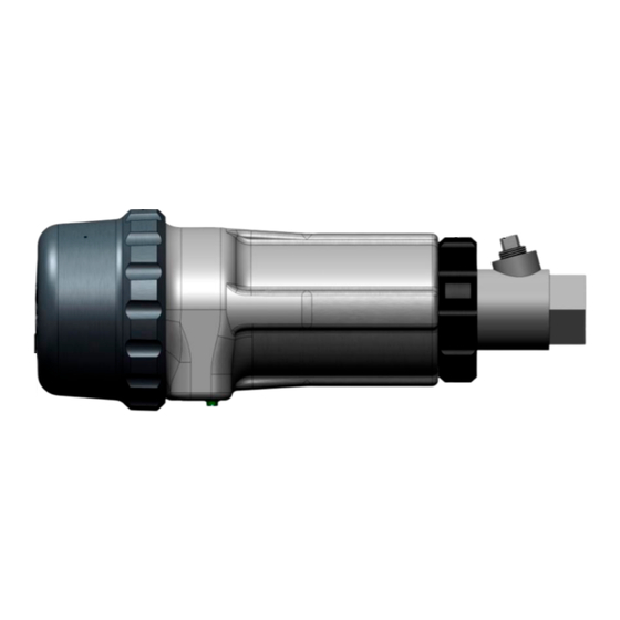
Summary of Contents for Forney IDD-II
- Page 1 IDD Flame Detector Heads Standard Models: IDD-II, IDD-IIL, IDD-IIU, and IDD-Ultra CEX Models: IDD-IICEX, IDD-IILCEX, IDD-IIUCEX 372000-05 Rev J...
- Page 2 Forney supervision. PROPRIETARY NOTICE The contents of this publication are proprietary data of Forney Corporation. Reproduction or use of any part of the publication for purposes other than the support of the equipment for which it is published is permissible only if expressly authorized in writing by Forney.
-
Page 3: Table Of Contents
IDD Flame Detector Heads Manual 372000-05 Rev J TABLE OF CONTENTS Section 1 Description ..........................3 Figure 1 Dimensional drawing – IDD Standard housing ..............3 1.1 IDD CEX ............................4 Figure 2 Dimensional drawing – IDD CEX..................4 1.2 Mechanical Specifications ....................... 5 1.3 Safety ............................... -
Page 4: Section 1 Description
372000-05 Rev J Section 1 Description The Forney IDD flame detector heads are non-repairable devices that generate an AC signal of variable amplitude and frequency proportional to a burner’s flame intensity. The detector head transmits the signal through a four-conductor cable to an applicable Forney flame amplifier. -
Page 5: Idd Cex
IDD Flame Detector Heads Manual 372000-05 Rev J IDD CEX Figure 2 Dimensional drawing – IDD CEX Housing Material: Aluminum Alloy, A 380 Window joints are cemented using Aremco bond 568 high temperature epoxy with a temperature index of -204C ... -
Page 6: Mechanical Specifications
90 degrees Recommended Viewing Angle 3 to 5 degrees 3 to 5 degrees Temperature Rating Operating: Operating: IDD-II, IDD-IIL and IDD-IIU IDD-II, IDD-IIL and IDD-IIU F to 140 F (0 C to 60 F to 140 F (0 C to 60... -
Page 7: Safety
IDD Flame Detector Heads Manual 372000-05 Rev J Safety The IDD model flame detector heads’ voltage point is not accessible under normal operating conditions. However, users should follow appropriate electrical safety procedure when installing the flame detector. Electrical power should always be removed from the flame detector amplifier before installing or replacing a flame detector head assembly. -
Page 8: Section 2 Installation
The location and sighting instructions listed in the following sections are general guidelines for the location of the detector. Consult Forney for application specific guidance on installation. The detector provides feedback to a Forney Flame Amplifier which goes onto the burner management system (BMS). -
Page 9: Idd-Cex Mounting Flange
IDD Flame Detector Heads Manual 372000-05 Rev J flame detector should be sighted so it does not detect the igniter flame. The detector should have an unrestricted view of flame as far as possible. Physical obstructions such as air register blades, interfering vanes, or other hardware should be cut away or notched so they do not fall within the detector’s line of sight as shown in Figure 3. -
Page 10: Figure 4 Detector Location Vs. Secondary Air Rotation
IDD Flame Detector Heads Manual 372000-05 Rev J Figure 4 Detector Location VS. Secondary air rotation If combustion air enters the furnace with a rotational movement of sufficient velocity to deflect pilot flame in direction of rotation, position the detector 0 to 30 degrees downstream of the pilot burner and close to the periphery of the throat where the ultraviolet radiation is at a maximum. -
Page 11: Figure 5 Idd Direct Mount Arrangement
NOTE: If freezing temperatures are expected at the detector head, Forney recommends heat tracing the detector sight tube. Contact Forney for additional details. CAUTION: To ensure safe and reliable detection it is the responsibility of the commissioning engineer to carry out flame failure testing after programming the detector. -
Page 12: Figure 6 Idd Swivel Mount Arrangement
IDD Flame Detector Heads Manual 372000-05 Rev J Figure 6 IDD Swivel Mount Arrangement Cable support bracket is required on Standard IDD when a cooling chamber is not used. Figure 7 IDD Direct Mount with Cooling Chamber Figure 8 IDD Swivel Mount Arrangement with Cooling Chamber... -
Page 13: Figure 9 Idd-Cex Direct Mount Arrangement
IDD Flame Detector Heads Manual 372000-05 Rev J Figure 9 IDD-CEX Direct Mount Arrangement Figure 10 IDD-CEX Swivel Mount Arrangement... -
Page 14: Figure 11 Idd-Cex Direct Mount Arrangement With Cooling Chamber
IDD Flame Detector Heads Manual 372000-05 Rev J Figure 11 IDD-CEX Direct Mount Arrangement with Cooling Chamber Figure 12 IDD-CEX Swivel Mount Arrangement with Cooling Chamber... -
Page 15: Detector Wiring
Figure 13 Sample Wiring Diagram for IDD Detector Head to Amplifier Refer to specific Forney Amplifier manual for specific wiring instructions for other amplifiers. Section 3 Commissioning Before commissioning, complete all of the installation instructions. -
Page 16: Section 4 Operation
IDD Flame Detector Heads Manual 372000-05 Rev J Section 4 Operation The IDD detector head is sighted at the first 1/3 of the flame or the primary combustion zone of the burner. The radiant energy from the flame is viewed either directly through a straight piece of pipe or transmitted to the surface of the detector cell through a fiber-optic assembly. -
Page 17: Section 6 Maintenance
The IDD detector head is a non-repairable device and requires no maintenance other than periodically cleaning the cell surface. The appropriate cleaning schedule is determined by the quality and cleanliness of the cooling-/seal-air source. Forney recommends the use of a non-oily cleaning solution and a soft lint- free cloth for lens cleaning. -
Page 18: Section 9 Parts
38321-23 IDD-IIL IR Detector (700 to 3300 nanometers; for lignite) 38321-29 IDD-Ultra UV Detector (200 to 425 nanometers) 399854-xx Detector cable with connector (-xx consult Forney for available lengths) 364524-01 Cable support bracket 381071-01 Cooling air chamber (Standard IDD version) 1”...


Need help?
Do you have a question about the IDD-II and is the answer not in the manual?
Questions and answers