Table of Contents
Advertisement
Quick Links
Advertisement
Table of Contents

Related Manuals for Forney UV-4


Summary of Contents for Forney UV-4
- Page 1 UV-4 Flame Detector 372000-28 Rev J...
- Page 2 All personnel should become thoroughly familiar with the contents of this manual before attempting to use the UV-4 Flame Detector. Because it is virtually impossible to cover every situation that might occur during operation and maintenance of the equipment described in this publication, personnel are expected to use good engineering judgment when confronted with situations that are not specifically mentioned herein.
-
Page 3: Table Of Contents
Section 5 Operation ...................... 7 Normal Operation ..........................7 Self-Test Operation .......................... 7 Section 6 Maintenance ....................7 Section 7 Troubleshooting ................... 8 Table 1 UV-4 Flame Detector Troubleshooting ................8 Section 8 Storage ......................8 Section 9 Return or Repair Service ................9... -
Page 4: Section 1 General Description
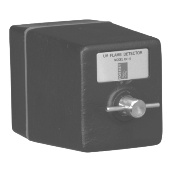
The UV-4 flame detector includes two major subassemblies: a head assembly and a base assembly. The head assembly (figure 1) consists of a machined housing that contains the internal electronics of the flame... - Page 5 A six-position electrical connector mates with a corresponding connector in the base assembly to facilitate installation or field replacement. Forney offers UV-4 base assemblies having several different configurations. Figures 2 through 4 illustrate the major physical variations. The primary functional differences are as follows: •...
- Page 6 UV-4 Flame Detector 372000-28 Rev J Figure 4 Base Assemblies with Fiber-Optics Light Guide...
-
Page 7: Mechanical Specifications
MS3112E10-6P (units with bulkhead connector only) A prefabricated four-wire, 2 –18 AWG and 2 – 20 AWG, shielded cable assembly is available from Forney. Cable signal/connector pin assignments are as follows: Pin A shutter voltage (green wire – 18 AWG) Pin B common ground (black wire –... -
Page 8: Section 2 Safety
NOTICE twist the connector barrel (figure 5). Twisting could cause the wires to become disconnected from solder connections inside the connector barrel. Figure 5 Cable Connections to Detector Head (IDD Detector Head shown instead of UV-4 shown for illustration purposes) -
Page 9: Section 3 Commissioning
4. After checkout, return the system to normal configuration. Section 4 Removal / Installation The UV-4 flame detector is designed for front-mounted, direct-view, or fiber-optic sighting of the burner flame. Initial installation of a new flame detector normally is accomplished with the furnace cold and depressurized. -
Page 10: Section 5 Operation
Section 5 Operation The Forney UV-4 detector normally is sighted on the primary combustion zone of a burner, and light from the burner flame passes through a sight tube or a fiber-optic light guide to an opening in the base assembly housing. -
Page 11: Section 7 Troubleshooting
2. Check for broken cable wire. 3. Reroute cable if not in a shielded cable tray. 4. Replace detector. Section 8 Storage Store the UV-4 Detector in its shipping box until used. See the mechanical specifications for storage temperature ranges. -
Page 12: Section 9 Return Or Repair Service
Section 9 Return or Repair Service Forney Corporation warrants this product to be free of defective material and workmanship. Forney will repair or replace this equipment if it is found to be defective upon receipt, but not later than 90 days from the date of shipment.
Need help?
Do you have a question about the UV-4 and is the answer not in the manual?
Questions and answers