Table of Contents
Advertisement
Quick Links
Download this manual
See also:
Maintenance Manual
Advertisement
Table of Contents

Related Manuals for Pop PNT800A


Summary of Contents for Pop PNT800A
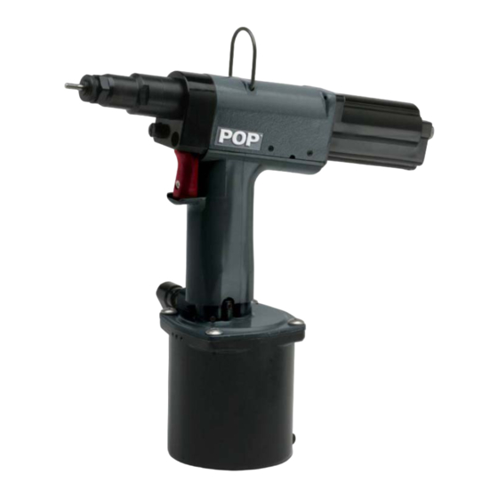
- Page 1 POP NUT ™ Tool PNT800A Maintenance Manual...
- Page 2 Table 1 lists the POP NUT™ blind rivet nuts that can be fastened using this tool. The Nosepiece and Mandrel must be changed to fit some sizes of POP NUT™. (See Table 5, Mandrel and Nosepiece Requirements table in the Specification section) Table 1: POP NUT™...
-
Page 3: Safety Instructions
Safety Instructions TO INSURE PROPER FUNCTIONING AND SAFE OPERATION READ THIS MANUAL CAREFULLY BEFORE SETTING UP OR OPERATING THE POP NUT SERIES TOOLS DEFINITIONS: • CAUTION! – Failure to observe this precaution could result in physical damage or minor injury. -
Page 4: Specifications
0.5 - 0.6MPa (5 - 6 bar) (72.5 - 87 psi) Hydraulic Oil See Table 3, Specified Hydraulic Oils Setting capacity See Table 1, POP NUT™ blind rivet nut range = 72.7 dB(A), L = 77.6 dB(A), Aeq,T Tool Noise Level = 106.3 dB(C) -
Page 5: Tool Parts
Air Hose Chamber (Not Included) Figure 2: Tool Parts Diagram Packaged Accessories Table 4: Packaged Accessories Part No. Item PNT800A-T PNT800A-POP NUT™ Tool PNT600-132 Hook PNT600-133 Hex wrench 1.5 mm DPN907-006 Cap screw M4 X 20 DPN277-179 POP NUT™ Mandrel Release... - Page 6 Table 5: Mandrel and Nosepiece requirements Flat Nosepiece Mandrel Thick Wall M8X1.0 Thread size I.D. (Std & ST) POP NUT Tool Part No. POP NUT Thread size Part No. I.D. Part No. Thread size M3X0.5 PNT800A-3 PNT600-02-3 φ4.0 PNT600-01-3 M3X0.5 M4X0.7...
-
Page 7: Pnt800A Diagram
PNT800A Diagram ® (*) These items require Loctite 242 adhesive. Shanghai Huiyu Electronics Technology Co., Ltd. Tel:+86-21-54721680 Fax:+86-21-54721681 Web: www.huiyutools.cn... - Page 8 Shanghai Huiyu Electronics Technology Co., Ltd. Tel:+86-21-54721680 Fax:+86-21-54721681 Web: www.huiyutools.cn...
-
Page 9: Parts List
Parts List Item Part No. Description Item Part No. Description PNT600-01-6P Mandrel M6 PNT600-39 Truss Head Screw PNT600-02-6 Nose Piece M6 DPN277-183 Chamber PNT600-03 Lock Nut PNT600-41A R Joint Adapter PNT600-04A Nose Housing DPN900-021 O-Ring DPN277-001 Spin Pull Head Case PNT600-43 R Joint Spacer DPN277-002... - Page 10 M Valve Rod PNT600-02-5 Nose Piece M5 PNT600-104 Motor Case End PNT600-02-8 Nose Piece M8 PNT600-105 Washer DPN277-179 POP NUT Mandrel Release DPN900-044 O-Ring PNT600-107 O-Ring Holder *See table 5 for additional Mandrels and Nosepieces DPN900-045 O-Ring DPN902-002 Retaining Ring...
-
Page 11: Tool Setup
Tool Setup Initial Setup 1. Check that the correct Nosepiece and Mandrel are fitted for the POP NUT™ to be installed. See the Basic Tool Operation section for proper tool adjustment. 2. Connect an air fitting to the Swivel Air Fitting of the tool. The Swivel Air Fitting is a 1/4 NPT thread. -
Page 12: Mandrel And Nosepiece Installation
3. Remove the Nosepiece from the tool by loosening the Lock Nut and unscrewing it (Figure 4). 4. Insert the POP NUT™ Mandrel Release tool over the Mandrel and into the Nose Housing. 5. Push Mandrel Release into the tool in order to disengage the Lock Pin Holder from the Mandrel. -
Page 13: Basic Tool Operation
Mandrel & Nosepiece Adjustment 1. Verify that the correct Mandrel and Nosepiece are fitted to the tool for the desired POP NUT™ (See Table 5, Mandrel and Nosepiece Requirements table in the Specifications section). -
Page 14: Tool Operation
Figure 8: Loading the POP NUT™ onto tool Installing the POP NUT™ into the work piece 1. With the POP NUT™ mounted on the Mandrel, insert it perpendicularly into the hole of the work piece 2. Pull trigger and hold it in order to install the insert 3. - Page 15 Not OK Not OK Figure 10: Proper insertion of POP NUT™ threaded inserts into an application *Disengaging the tool from the insert WARNING! If you let go of the trigger during the installation sequence, the insert may not set completely, the hydraulics will reset and the tool will not automatically unthread from the insert.
-
Page 16: Setting Tool Stroke
Stroke Adjustment 1. Loosen the M3 Lock Screw on the Control Nut using a 1.5mm Hex Wrench. 2. Set Stroke to the value of “E” as determined by the stroke formula below or from the POP NUT™ Stroke Charts. 3. Adjust the stroke by turning the Control Knob (¼ turn ~ 0.2mm) Stroke Scale a. -
Page 17: Stroke Setting For Standard Pop Nuts
Use the following procedure to determine the proper setting requirements for the ST, TK, TL, TH Series of POP NUTs™ or use the POP NUT™ Stroke Charts: 1. Determine the Installed Length, “IL” of the POP NUT™ being used. This information can be found in the Emhart POP NUT™ Blind Rivet Nut catalog. - Page 18 Adjust stroke Control Knob by 1/4 rotations. If the Control Knob is rotated counter-clockwise by a large amount to increase the stroke, it may cause stripping or sticking of Mandrel and/or POP NUT™ threads. POP NUT™ Stroke Charts Thick Wall, Standard POP NUTs™...
- Page 19 Thick Wall, “ST” POP NUTs ST Series Open End (Inch) 0.00 0.01 0.02 0.03 0.04 0.05 0.06 0.07 0.08 0.09 0.10 0.11 0.12 0.13 0.14 0.15 0.16 0.17 0.18 0.19 0.20 0.21 0.22 0.23 0.24 0.25 0.26 0.27 Workpiece Thickness (in)
- Page 20 Thin Wall, TK & TL POP NUTs TK /TL Series Open End (Inch) 0.00 0.01 0.02 0.03 0.04 0.05 0.06 0.07 0.08 0.09 0.10 0.11 0.12 0.13 0.14 0.15 0.16 0.17 0.18 0.19 0.20 0.21 0.22 0.23 0.24 0.25 0.26 0.27 0.28 0.29 0.30 0.31 0.32 0.33 0.34 0.35 0.36...
- Page 21 Thin Wall, TH POP NUTs TH Series Open End (Inch) 0.00 0.01 0.02 0.03 0.04 0.05 0.06 0.07 0.08 0.09 0.10 0.11 0.12 0.13 0.14 0.15 0.16 0.17 0.18 0.19 0.20 0.21 0.22 0.23 0.24 0.25 0.26 0.27 0.28 0.29 0.30 0.31 0.32 0.33...
-
Page 22: Maintenance
Over time, debris can stick to the Mandrel reducing its lubrication making it difficult to mount POP NUTs™ or causing premature wear or jams. Lube the Mandrel with 1 drop of oil. Use the same oil that is used with the Air Lubricator or an ISO VG 32 type oil. - Page 23 11. Re-assemble to tool. 12. Turn the Control Knob clock-wise until it reaches the end of its movement. 13. Set a POP NUT™ without a work piece and check the stroke. The stroke should be 1.3mm or less. 14. If the stroke is greater than 1.3mm, check the assembly length of the T-Valve Push Rod.
-
Page 24: Recharging Hydraulics
Stroke Lock Screw position Figure 18: T-Valve Push Rod assembly re-assembled to tool Recharging Hydraulics • If the stroke gets too short and the tool is unable to properly set an insert the Hydraulic Oil may need to be recharged. Note: If the stroke is still inadequate after recharging, the Hydraulic Seals may need to be replaced. - Page 25 Back-up Ring Penta Seal Handle Figure 20: Re-filling Hydraulic Oil 8. Replace the Air Piston Assembly and push it into the Handle slowly, 5 times, and then remove it 9. Check to see if the oil level has fallen or if there are air bubbles present in the oil 10.
-
Page 26: Troubleshooting
Action Section Cannot thread the Incorrect Mandrel and Change to the correct parts Specifications, POP NUT™ onto Nosepiece for the POP Nut you are Table 5 Mandrel using. Mandrel threads are Replace the Mandrel Tool Setup damaged. Check tool for proper stroke... - Page 27 Mandrel rotates M-Valve Rod (#103) at back Remove Rear Case (#45) and PNT800A Diagram clockwise as soon of Air Motor is stuck inspect M Valve End (#98) and as air is supplied to M Valve Rod (#103)
Need help?
Do you have a question about the PNT800A and is the answer not in the manual?
Questions and answers