Table of Contents
Advertisement
Advertisement
Table of Contents

Related Manuals for TradeWeld GENX MIG2800S INDUSPRO


Summary of Contents for TradeWeld GENX MIG2800S INDUSPRO
-
Page 3: Table Of Contents
CONTENTS Contents & Explanation ··········································································································· 2 Safety Warning & Duty Cycle Explained ···················································································· 3 Machine Description ··············································································································· 4 Technical Specification ··········································································································· 5 Accessories & Consumables ··································································································· 6 Assembly of Bottle Bracket ····································································································· 7 Operation of MIG / LIFT TIG / STICK ·························································································· 8-9 Installation of MIG / LIFT TIG / STICK ························································································... -
Page 4: Safety Warning & Duty Cycle Explained
SAFETY WARNING In the process of welding, there could be possibilities of injury, so please take protection into consideration during operation. For more details please read the Operator Safety Guide, which complies with the preventive requirements of the manufacturer. Electric shock——Can kill ! Set the earth fitting according to applying standard. -
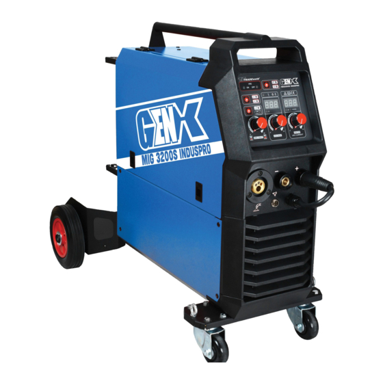
Page 5: Machine Description
MACHINE DESCRIPTION Thank you for purchasing a TRADEweld product. The TRADEweld MIG2800S INDUSPRO is manufactured with the most advanced technology in the world. The principle of this technology is to transform the power frequency of 50Hz/60Hz into direct current and invert it into high frequency (33 KHz) through high-power IGBT device’s, then a voltage-drop will be created through the high-power D.C power... -
Page 6: Technical Specification
TECHNICAL SPECIFICATIONS MIG2800S MIG3200S MODEL INDUSPRO INDUSPRO AC220V±15% AC380V±15% Rated Input Voltage 1Phase 3Phase Frequency(Hz) 50/60 50/60 NO Load Voltage 16.7A 51.6A Rated Input Current 50A-250A 50A-300A Output Current Range 16.5V-29V 16.5V-26.5V Output Voltage Range 18.5A 58.4A Rated Input Current 25A-300A 25A-250A Output Current Range... -
Page 7: Accessories & Consumables
ACCESSORIES & CONSUMABLES Supplied with the MIG2800S and MIG3200S in the box is the following: 1 x MB 25 torch 1 x earth clamp and cable 1 x 2m gas pipe 1 x electrode holder and cable 2 x hose clamp 1 x SR26 TIG torch MB25 TORCH EWB00307... -
Page 8: Assembly Of Bottle Bracket
ASSEMBLY OF BOTTLE BRACKET If the components are packed separately, users should install them as following: Fit the bottle holder left and right support brackets and axle to the bottle holder with 6 x M5 screws as figure 1. ⚫ Fit the wheels to the axle with washers and circlip as figure 2. - Page 9 OPERATION OF MIG / LIFT TIG / MMA The machine is equipped with a power voltage regulator. When power voltage moves between ± 15 % of rated voltage, it will still work normally. Should an extension cable be required (not recommended), a cord gauge of not less than 2.5mm is suggested and not longer than 10 metres.
-
Page 10: Operation Of Mig / Lift Tig / Stick
LIFT TIG Switch the MODE selector to TIG You will need: A TIG torch with a valve and a 10-25 dinse connector, An Argon flow Meter and Argon gas, Consumables such as Thoriated tungsten, ceramic shroud, back cap, collet and collet body. Connecting: The TIG torch is connected to the negative terminal and the earth is connected to the positive terminal, connect the gas hose to the Argon flow meter on the gas bottle and set gas flow between 10-15 LPM and sharpen the tungsten tip. -
Page 11: Installation Of Mig / Lift Tig / Stick
INSTALLATION OF MIG / LIFT TIG MIG INSTALATION TIG INSTALATION... - Page 12 INSTALLATION OF MMA / SPOOL GUN MMA INSTALATION SPOOL GUN INSTALATION...
-
Page 13: Panel Functions
PANEL FUNCTIONS Four core socket 2T/4T switch button Voltage meter Burn back adjustment button Euro Adapter MIG/TIG/MMA switch button Current meter Quick feed button Current adjustment button VRD indicator Negative output terminal MIG torch / Spool Gun Voltage adjustment button Positive output terminal selector Arc trait adjustment button... -
Page 14: Specification Chart Guide Lines
MIG CHART GUIDELINE Wire Plate Wire Weldin Gas flow Interval Current Voltage extensio thickness diameter g speed rate (cm/mi (mm) (mm) (mm) (L/min) (mm) (V) 0.8,0.9 60~70 16~16.5 50~60 0.8,0.9 75~85 17~17.5 50~60 10~15 0.8,0.9 80~90 16~16.5 50~60 10~15 0.8,0.9 95~105 17~18 45~50... - Page 15 MIG CHART GUIDELINE CONTINUED… Welding Plate Wire Welding Wire Gas flow Current Voltage thickness diameter speed extension rate vertical angle(°) (cm/min) (mm) (mm) (A) (V) (mm) (L/min) 0.8,0.9 45Deg 70~80 17~18 50~60 10~15 0.9,1.0 45Deg 85~90 18~19 50~60 10~15 1.0,1.2 45Deg 100~110 19~20...
-
Page 16: Typical Mig Process Settings
TYPICAL MIG PROCESS SETTINGS NOTE These settings are guidelines only. Material and wire type, joint design, setup position, shielding gas, etc. affect settings. Test welds to be sure they comply with specifications. Material thickness Convert material thickness determines weld to Amperage (A) parameters (0.024mm = 1 Ampere) MILD STEEL... -
Page 17: Operating Precautions
OPERATING PRECAUTIONS Operating Environment The machine can perform in environments where conditions are dry with a max humidity of 60%. Ambient temperature should be between -10 to +40 degrees centigrade. Avoid operating machine in direct sunshine, rain, or snow. Avoid operating the machine in environments where there is pollution or high concentrations of dust or corrosiveness gas in the air. -
Page 18: Maintenance
MAINTENANCE WARNING! Before maintenance and checking, power must be turned off, Before opening the cover disconnect the machine from electricity! 1. Remove dust with dry, clean compressed air regularly, if the welding machine is operated in an area where the air is polluted with smoke and dust, the machine needs to be cleaned regularly, remove dust monthly. -
Page 19: Daily Checking
DAILY CHECKING The following can cause problems with welding: Fittings, welding materials, environmental factors, power supply and welding techniques. User must try to improve working conditions. Position Checking keys Remarks 1. Condition of switches and potentiometers. Control 2. Volt and Amp display. Replace if faulty. -
Page 20: Troubleshooting & Fault Finding
TROUBLESHOOTING AND FAULT FINDING Notes: only attempt to repair this machine if you have knowledge and understanding of electronic components and the dangers of electricity and components holding a charge of high voltage electricity. Before maintenance contact the agent for authorization is suggested WARNING! Experimentation and careless maintenance may lead to more problems to the machine. -
Page 21: Explosion Diagrams & Part List
EXPLOSION DIAGRAM MIG 2800S and MIG 3200S The pictures or lay out may differ from actual machine... -
Page 22: Circuit Diagram
PART LIST NAME PART NO. NAME PART NO. NAME PART NO. BOTTOM CHASIE COPPER CONNECTOR POWER CABLE GLAND 10-25 DINSE CONNECT + EWC0060 RIGHT SIDE COVER ROCKER SWITCH EWS00019 10-25 DINSE PLUG EWC0058 MAIN CONTROL BOARD PLASTIC BACK PANEL 4 PIN METAL MIC PLUG EW00046 SUPPORTS 4 PIN CABLE MIC PLUG... -
Page 23: Warranty & Owners Records
WARRANTY L&G Tool and Machinery Distributors warrant to the original purchaser only, that this product is free from defects in material and workmanship. Subject to certain exceptions, L&G Tools & Machinery Distributors will repair or replace any part on this product which, after examination, is determined by us to be defective in material or workmanship for a period of twelve (12) months after the date of purchase unless otherwise noted.
Need help?
Do you have a question about the GENX MIG2800S INDUSPRO and is the answer not in the manual?
Questions and answers