Advertisement
Table of Contents
- 1 Table of Contents
- 2 Contents & Explanation of Symbols
- 3 Safety Warning & Duty Cycle Explained
- 4 Machine Description
- 5 Technical Specification
- 6 Accessories & Consumables
- 7 Installation & Operation of MIG & MMA & TIG
- 8 Front Panel Layout
- 9 Knob Functions
- 10 Typical MIG Process Settings
- 11 Operating Precautions
- 12 Maintenance
- 13 Daily Checking
- 14 Troubleshooting & Fault Finding
- 15 Explosion Diagrams & Part List
- 16 Warranty & Owners Records
- Download this manual
Advertisement
Table of Contents

Related Manuals for TradeWeld MIG 250M


Summary of Contents for TradeWeld MIG 250M
-
Page 2: Table Of Contents
CONTENTS Contents & Explanation of Symbols ······················································································· 2 Safety Warning & Duty Cycle Explained ················································································· 3 Machine Description ············································································································ 4 Technical Specification ········································································································ 5 Accessories & Consumables ································································································ 6 Installation & Operation of MIG & MMA & TIG ·········································································· 7 Front Panel layout ···············································································································... -
Page 3: Safety Warning & Duty Cycle Explained
SAFETY WARNING In the process of welding, there could be possibilities of injury, so please take protection into consideration during operation. For more details please read the Operator Safety Guide, which complies with the preventive requirements of the manufacturer. Electric shock——Can kill ! Set the earth fitting according to applying standard. -
Page 4: Machine Description
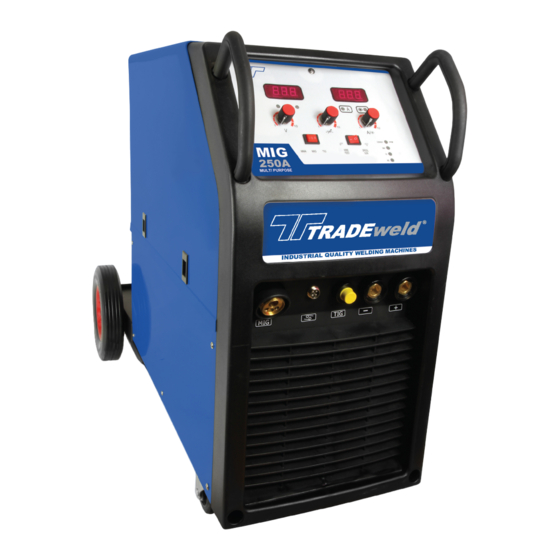
CAN DAMAGE MACHINE AND VOID WARRANTY MACHINE DESCRIPTION Thank you for purchasing a TRADEweld product. The TRADEweld Mig 250 M is a Multi-Process welder that incorporates Mig, TIG and MMA welding in one unit. Adopting the most advanced inverter technology, it uses power Inverters and PWM technology, which works by rectifying the mains AC input voltage. -
Page 5: Technical Specification
TECHNICAL SPECIFICATIONS MODEL MIG 250M AC220V±10% Rated Input Voltage 1Phase Frequency(Hz) 50/60 Rated Input Current 51.6A Output Current Range 50A-250A Output Voltage Range 14V-26.5V Output current range 15A – 250A Output voltage H.F Function Trigger start Output Current Range 15A-250A... -
Page 6: Accessories & Consumables
ACCESSORIES & CONSUMABLES Supplied with the MIG250M in the box is the following: 1 x MB 25 torch 1 x earth clamp and cable 1 x 2m gas pipe 1 x electrode holder and cable 2 x hose clamp 1 x SR26 TIG torch MB25 TORCH EWB00307... -
Page 7: Installation & Operation Of Mig & Mma & Tig
INSTALLATION & OPERATION OF MIG The machine is equipped with a power voltage regulator. When power voltage moves between ± 10 % of rated voltage, it will still work normally. Should an extension cable be required (not recommended), a cord gauge of not less than 2.5mm is suggested and not longer than 10 metres. -
Page 8: Front Panel Layout
FRONT PANEL LAYOUT The pictures or lay out may differ from actual machine... -
Page 9: Knob Functions
KNOB FUNCTIONS Wire Speed & MMA & TIG Amperage: In MMA mode you can adjust the output amperage. In MIG mode it adjusts the wire speed and proportionately affects the amperage. The increase in wire speed determines the amount of weld penetration. -
Page 10: Typical Mig Process Settings
TYPICAL MIG PROCESS SETTINGS NOTE These settings are guidelines only. Material and wire type, joint design, setup position, shielding gas, etc. affect settings. Test welds to be sure they comply with specifications. Material thickness Convert material thickness determines weld to Amperage (A) parameters (0.024mm = 1 Ampere) 3mm = 125 A... -
Page 11: Operating Precautions
OPERATING PRECAUTIONS Operating Environment The machine can perform in environments where conditions are dry with a max humidity of 60%. Ambient temperature should be between -10 to +40 degrees centigrade. Avoid operating machine in direct sunshine, rain, or snow. Avoid operating the machine in environments where there is pollution or high concentrations of dust or corrosiveness gas in the air. -
Page 12: Maintenance
Note: Continuous overload operation will damage the welding power source. In these cases, the damage is not covered by warranty repair. WARNING! This machine produces an electromagnetic field during operation. This field may under some circumstances interfere with active or passive medical implants. To reduce the risk of serious or fatal injury, we recommend persons with medical implants to consult their physician and the medical implant manufacturer before operating this machine. -
Page 13: Daily Checking
is used • Earth leakage-circuit breaker should be used with this machine!!! • During welding, DO NOT pull out or insert any plugs or cables, it can lead to life-threatening danger and cause damage to the machine. • Before connecting cables make sure the power is off. The correct way is to connect the cables to the machine first, and make sure they are firmly tightened and then connect the power plug to the power source. -
Page 14: Troubleshooting & Fault Finding
TROUBLESHOOTING AND FAULT FINDING Position Checking keys Remarks 1. Condition of switches and potentiometers. Control 2. Volt and Amp display. Replace if faulty. panel 3. Warning lights 1. Check if there is air flow. Check for obstructions at fan intake or Cooling fan 2. -
Page 15: Explosion Diagrams & Part List
4. Bad connections - Hot/bad connections or points on earth cable, electrode holder & torches can cause current to drop or be unstable. If the machine fails to work after maintenance and checks, please contact your local distributor or our after- sale service center. MIG 250M EXPLOSION DIAGRAM... -
Page 16: Warranty & Owners Records
PART LIST NAME PART NO. NAME PART NO. NAME PART NO. NAME PART NO. WIRE FEED PCB PK-02- BASE PLATE LED BOARD EWPCB0002 GAS BOTTLE BRACKET CHOKE POT KNOB EWS00013 RECTIFIER DIODE EW00831 GAS BOTTLE SUPORT TOP PCB EWPCB00014 ROCKER SWITCH 2P 2 WHEEL MOTOR EW00090 REAR WHEEL AXIL... - Page 17 in material and workmanship. Subject to certain exceptions, L&G Tools & Machinery Distributors will repair or replace any part on this product which, after examination, is determined by us to be defective in material or workmanship for a period of twelve (12) months after the date of purchase unless otherwise noted. Return of the product and all its accessories to the Retailer is required, together with a copy of the proof of purchase should be included with the returned product.
Need help?
Do you have a question about the MIG 250M and is the answer not in the manual?
Questions and answers