Table of Contents
Advertisement
Quick Links
Advertisement
Table of Contents

Related Manuals for Ryobi RBV-3350


Summary of Contents for Ryobi RBV-3350
-
Page 2: Specifications
THANK YOU FOR BUYING A RYOBI BLOWER/VACUUM Your new blower/vacuum has been engineered and manufactured to Ryobi’s high standard of dependability, ease of operation and operator safety. Properly cared for, it will give you years of rugged, trouble free performance. If you use your blower/vacuum properly and only for what it is intended, you will enjoy years of safe, reliable service. -
Page 3: Important Safety Instructions
INTENDED USE of electric shocks and the risk of injury and fire: Your Ryobi blower/vacuum has been designed for leaf clearing. This tool is intended for consumer The safety rules must be observed during tool use. -
Page 4: Specific Safety Instructions
IMPORTANT SAFETY INSTRUCTIONS Do not use on steps, a ladder, roof top, tree, or Never use blower to spread chemicals, fertilizers, other unstable support. Stable footing on a solid or any other toxic substances. Spreading these surface enables better control of the blower/vac in substances could result in serious injury to the unexpected situations. -
Page 5: General Safety Rules
IMPORTANT SAFETY INSTRUCTIONS Rotating impeller blades can cause severe injury. cables measuring up to 25m must be at least 1.5 Stop the engine before opening the vacuum door , and 2.5 mm for cables longer than 25m. or installing/changing tubes. Do not put hands or Always roll the whole cable off the reel before use. -
Page 6: Personal Safety
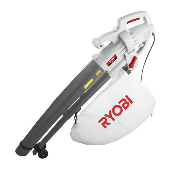
IMPORTANT SAFETY INSTRUCTIONS b) Avoid body contact with earthed or grounded g) If devices are provided for the connection of surfaces such as pipes, radiators, ranges and dust extraction and collection facilities, ensure refrigerators. There is an increased risk of these are connected and properly used. - Page 7 DESCRIPTION 1. Harness hook 7. Collection bag 2. On/Off switch trigger 8. Wheel 3. Rear handle 9. Lower blower/vacuum tube 4. Power cable 10. Upper blower/vacuum tube 5. Function change lever 11. Front handle 6. Vacuum bag holder...
-
Page 8: Packing Contents
UNPACKING CAUTION. This packaging contains If any parts are found to be missing, the machine sharp objects. Take care when and its accessories should be returned together in unpacking. Remove the machine, their original packaging to the retailer. Do not throw together with the accessories supplied, from the the packaging away, keep it safe throughout the packaging. -
Page 9: Attaching The Wheels
ASSEMBLY ATTACHING THE BLOWER/VACUUM TUBES TO THE MAIN BODY Before installing the upper blower/vacuum tube section remove the 2 screws in place B & C. Push the upper blower/vacuum section firmly into the main body until it clicks into place. Use a connection screw in place D, Fig.3, reinstall the two screws in place B &... -
Page 10: Operation
OPERATION WARNING. Do not allow familiarity with products to make you careless. Remember that a careless fraction of a second is sufficient to inflict severe injury. WARNING. Always wear eye protection with side shields marked to comply with ANSI Z87.1. Failure to do so could result in objects being thrown into your eyes, resulting in possible serious injury. -
Page 11: Starting And Stopping
OPERATION STARTING AND STOPPING Connect the plug to main power supply. Squeeze the On/Off trigger (Fig.10) to start the blower/vacuum. To stop the blower/vacuum, simply release the trigger. OPERATING THE BLOWER To keep from scattering debris, blow around the outer edges of a debris pile. Never blow directly into the center of a pile. -
Page 12: General Maintenance
MAINTENANCE WARNING. Before inspecting, cleaning, WARNING. Do not at any time let brake or servicing the machine, shut off motor, fluids, gasoline, petroleum based wait for all moving parts to stop, and products, penetrating oils, etc., come in disconnect extension cord. Failure to contact with plastic parts. - Page 13 SYMBOLS Indicates danger, warning or caution. It means attention!!! Safety Alert Symbol Your safety is involved. Read Your Operator's Your manual contains special messages to bring attention Manual to potential safety concerns as well as operating and servicing information. Please read all the information carefully to ensure satisfaction and safe use.
- Page 14 NOTES...
- Page 15 NOTES...
- Page 16 NOTES...
Need help?
Do you have a question about the RBV-3350 and is the answer not in the manual?
Questions and answers
Is there a blow up diagram of this unit. A small bolt with a plastic tee piece on one end shot out of handle while assembling. Not first use.