Table of Contents
Advertisement
http://www.lge.co.kr
P/NO:3828TUL057B (S-9909)
Printed in CHINA
÷‚ÂÚÌÓÈ ÏÓÌËÚÓ
–ÛÍÓ‚Ó‰ÒÚ‚Ó ÔÓθÁÓ‚‡ÚÂΡ
OWNER'S MANUAL
StudioWorks 520Si
CH01
œÂ ‰ ̇˜‡ÎÓÏ ˝ÍÒÔÎÛ‡Ú‡ˆËË ¬‡¯Â„Ó ÏÓÌËÚÓ ‡,
ÔÓʇÎÛÈÒÚ‡, ‚ÌËχÚÂθÌÓ Ô Ó˜ËÚ‡ÈÚ ‰‡ÌÌÓÂ
ÛÍÓ‚Ó‰ÒÚ‚Ó Ë ÒÓı ‡ÌËÚÂ Â„Ó ‰Îˇ ËÒÔÓθÁÓ‚‡Ìˡ ‚
·Û‰Û˘ÂÏ.
HËÊ ‚Ô˯ËÚ ÌÓÏ ÏÓ‰ÂÎË Ë Ò ËÈÌ˚È ÌÓÏÂ
‡ÔÔ‡ ‡Ú‡.
›Ú‡ ËÌÙÓ Ï‡ˆËˇ ̇ıÓ‰ËÚÒˇ ̇ ˝ÚËÍÂÚÍÂ,
Ô ËÍÎÂÂÌÌÓÈ Í Á‡‰ÌÂÈ Ô‡ÌÂÎË ÏÓÌËÚÓ ‡.
¬ ÒÎÛ˜‡Â ÌÂÓ·ıÓ‰ËÏÓÒÚË ÂÏÓÌÚ‡ ÒÓÓ·¯ËÚ ˝ÚÛ
ËÌÙÓ Ï‡ˆÌ˛ ¬‡¯ÂÏÛ ‰ËΠÛ.
Internet Address:http://www.lg.ru
»ÌÙÓ Ï‡ˆËÓÌ̇ˇ ÒÎÛÊ·‡ LG Electronics (095)742-77-77
Advertisement
Table of Contents

Related Manuals for LG StudioWorks 520Si


Summary of Contents for LG StudioWorks 520Si
- Page 1 HËÊ ‚Ô˯ËÚ ÌÓÏ ÏÓ‰ÂÎË Ë Ò ËÈÌ˚È ÌÓÏ ‡ÔÔ‡ ‡Ú‡. ›Ú‡ ËÌÙÓ Ï‡ˆËˇ ̇ıÓ‰ËÚÒˇ ̇ ˝ÚËÍÂÚÍÂ, Ô ËÍÎÂÂÌÌÓÈ Í Á‡‰ÌÂÈ Ô‡ÌÂÎË ÏÓÌËÚÓ ‡. ¬ ÒÎÛ˜‡Â ÌÂÓ·ıÓ‰ËÏÓÒÚË ÂÏÓÌÚ‡ ÒÓÓ·¯ËÚ ˝ÚÛ ËÌÙÓ Ï‡ˆÌ˛ ¬‡¯ÂÏÛ ‰ËΠÛ. Internet Address:http://www.lg.ru »ÌÙÓ Ï‡ˆËÓÌ̇ˇ ÒÎÛÊ·‡ LG Electronics (095)742-77-77 Printed in CHINA P/NO:3828TUL057B (S-9909)
-
Page 2: Table Of Contents
Table of Contents Monitor Registration Notice.......................A1 Trademark Acknowledgments..............A1 Important Precautions On safety....................A2 On installation ..................A3 On cleaning....................A3 On repacking....................A3 Tilt/Swivel Base Installation....................A4 Installation Connections .....................A5 Location and Function of Controls Front View ....................A6 Rear View ....................A6 Image Control Panel ................A7 Power Management System, MPR II and DDC Power Management System..............A9 Low Radiation Compliance (MPR II)............A9... -
Page 3: Monitor Registration
Serial No. Notice All rights reserved. Reproduction in any manner, in whole or in part, is strictly prohibited without the written permission of LG Electronics Inc. Trademark Acknowledgments LG is a trademark of LG Electronics Inc. IBM is a registered trademark and VGA is a trademark of International Business Machines Corporation. -
Page 4: Important Precautions
Important Precautions This unit has been engineered and manufactured to assure your personal safety, but improper use can result in potential electrical shock or fire hazard. In order not to defeat the safeguards incorporated in this monitor, observe the following basic rules for its installation, use, and servicing. -
Page 5: On Installation
Important Precautions Keep children from dropping or pushing objects into the monitor's cabinet openings. Some internal parts carry hazardous voltages. Do not add accessories that have not been designed for this monitor. During a lightning storm or when the monitor is to be left unattended for an extended period of time, unplug it from the wall outlet. -
Page 6: Tilt/Swivel Base
Tilt/Swivel Base Turn Off the equipment and all attached options. Carefully set the monitor face-down with the underside facing you. Installation 1. Align the hooks on the tilt/swivel stand with the matching slots in the base of the monitor. 2. Insert the hooks into slots. 3. -
Page 7: Installation
Installation The supply voltage is marked on the ID label located on the rear panel of the monitor. If your local voltage is different, do not use the monitor and contact your supplier before using the display. Connections To connect your monitor after the video adapter is properly installed: 1. -
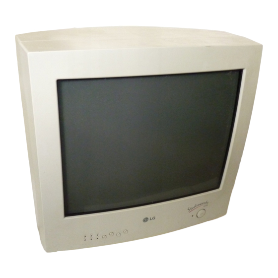
Page 8: Location And Function Of Controls Front View
Location and Function of Controls Front View Power On/Off Button Power Indicator Image Control Panel Brightness Contrast Rear View ID Label AC Power Connector Signal Cable... -
Page 9: Image Control Panel
Location and Function of Controls Power On/Off Button This Button is used to turn the power On or Off. Power Indicator The power indicator lights when the power is On, and indicates the operating status of the display. Contrast Adjust the display to the contrast desired. Move the thumbwheel located beneath this indicator to increase or decrease the display contrast. - Page 10 Image Control Panel Image Control Icons Listed below are the icons, icon names, and icon descriptions of the items. icon Description Horizontal To move picture image left and right. Position Moves the screen image left. + Moves the screen image right. Horizontal To adjust image width.
-
Page 11: Power Management System
Power Management System When used in conjunction with a PC having power saving circuitry, or a PC running screen blanking software this monitor automatically reduces its power consumption when the computer is not in use.The monitor has power-saving states, indicated by the light-emitting diode (LED) on the front panel.These power-saving states exceed the Environmental Protection Agency (EPA) Energy Star requirements using the methodology for Display Power Management Signals(DPMS). -
Page 12: General Operation
General Operation After following the installation instructions and getting familiar with the controls, you are ready to operate the monitor. 1. Turn on the monitor, PC and other peripherals you plan to use. 2. After the PC has booted (powered up and finished self-testing), enter a software application that uses the full screen display. -
Page 13: Troubleshooting
Troubleshooting The power LED is illuminated amber. Display power management mode. There is no active signal coming from the PC. The signal cable is not fastened securely. Check the computer power and graphics adapters configuration. The frequency of the signal from the video card is outside the operating range of the monitor. -
Page 14: Service
Service 1. Unplug the monitor from the wall outlet and refer servicing to alified service personnel when : The power cord or plug is damaged or frayed. Liquid has been spilled into the monitor. The monitor has been exposed to rain or water. The monitor does not operate normally following the operating instructions. - Page 15 Specifications Sync Signal type Type H. Sync V. Sync Separate sync H. Sync V. Sync Signal Connector Pin Assignment Separate Sync Green Blue Ground Self-Test Red Ground Green Ground Blue Ground Ground Ground Horiz.Sync Vert.Sync...
- Page 16 (With Tilt/Swivel Stand)) (WXDXH) 14.2 x 15.2 x 14.9 inch Weight (net) : 12.5 kg (27.6 lbs) Information in this document is subject to change without notice and does not represent a commitment on the part of LG Electronics Inc.
-
Page 17: Specifications
SPECIFICATIONS 1. PICTURE TUBE 3-2. Power Consumption Size : 15 inch (Flat Square Tube) MODE H/V SYNC POWER CONSUMPTION LED COLOR : In-line DefIection Angle : 90° less than 85 W NORMAL (ON) ON/ON GREEN Neck Diameter : 29.4mm less than 15 W STAND-BY OFF/ON Phosphor... - Page 18 2. MAIN BOARD (Solder Side) - 24 -...
- Page 19 PRINTED CIRCUIT BOARD 1. MAIN BOARD (Component Side) - 23 -...
- Page 20 SBHG1-A, T1.0 303-K30U BACK COVER 332-102H SCREW, PTP+4x40BP (FZMY) 231-048U TILT/SWIVEL 6871TVT109B PCB ASS'Y, VIDEO TOTAL 6871TMH113B PCB ASS'Y, MAIN 3313T15047B CHASSIS ASS'Y, MAIN TOTAL * Remark ‘L’ are local sourcing parts in China factory of the LG Electronics Inc.
- Page 21 WIRING DIAGRAM PW402 PW402A PW501 P501 s+ s- P902 W1 W2 AC Socket Signal Cable P302 P301 GND1 P304 - 7 -...
- Page 23 BLOCK DIAGRAM - 10 -...
- Page 24 DESCRIPTION OF BLOCK DIAGRAM 1. Primary Rectifier Circuit 7. Horizontal and Vertical Drive Circuit This circuit transform AC line voltage to DC voltage as This circuit take function, that are H/V-position, H/V- the supplied source for secondary circuit. size, side-pincushion, and trapezoid, with the output of It is operated by C905 (electrolytic capacitor) and microprocessor circuit.
- Page 25 TROUBLESHOOTING GUIDE BASIC GUIDE CHECK FOLLOW SMPS SECONDARY NO POWER B + OUTPUT. PROCEDURE CHECK FOLLOW HORIZONTAL NO RASTER OUTPUT PROCEDURE WAVEFORM. FOLLOW CHECK NO VERTICAL VERTICAL OUTPUT DEFLECTION WAVEFORM. PROCEDURE FOLLOW CHECK NO CHARACTER, VIDEO OUTPUT NO CONTRAST WAVEFORM. PROCEDURE FOLLOW OTHER PROCEDURES.
- Page 26 1. NO POWER NO POWER TROUBLE IN CHECK C905 F901, R901, DC VOLTAGE? D901, D902, D903, D904 DC=MORE THAN 130V CHECK TROUBLE IN CHECK T901 Q915, Q917, IC901,R902, IC901? PIN 4 ? R914, D906, D907 TROUBLE IN D906, D907, R906 TROUBLE IN CHECK D921, D922, D924, D928...
- Page 27 2. NO CHARACTER NO CHARACTER CHECK TROUBLE IN IC301 PIN 8 (8V)? IC302 12V LINE CHECK TROUBLE IN IC301 PIN 2, 4, 6 ? PC SIGNAL, C311, C331, C351 CHECK TROUBLE IN IC301 PIN 19 ? CLAMP CIRCUIT CHECK TROUBLE IN IC301 PIN 11, IC301 CIRCUIT 15, 18 ?
- Page 28 3. NO RASTER (LED COLOR IS GREEN) NO RASTER TROUBLE IN CHECK HEATER VOLTAGE CDT HEATER VOLTAGE? SUPPLY CIRCUIT (6.3 ± 0.6V) ( Q904, Q905, Q914) TROUBLE IN CHECK G1 SUPPLY CIRCUIT CDT G1 (0 ~ - 60V)? (D508, C636, Q509, Q510, ZD501 etc) CHECK FOLLOW...
- Page 29 4. TROUBLE IN H/V SIZE, H/V POSITION, S-PCC, TRAPEZOID NO ADJUSTED H-/V SIZE, POSITION, S-PCC, TRAP. CHECK TROUBLE IN IC401 PIN 17, 18, IC401 (MICOM) 19, 20, 30 ? TROUBLE IN SCL, SDA CIRCUIT - 18 -...
- Page 30 5. NO VERTICAL DEFLECTION NO V-DEFLECTION (ONE HORIZONTAL LINE) CHECK TROUBLE IN IC601 PIN 2 14V LINE, R612, C627 (14V)? CHECK TROUBLE IN IC601 PIN 5 -12V LINE, (-12V)? D515, R599, C538 CHECK TROUBLE IN IC701 PIN 21, 23? IC701 TROUBLE IN IC601, V- DEFLECTION CIRCUIT...
- Page 31 6. NO CONTRAST NO CONTRAST CHECK TROUBLE IN Q512 Q512? TROUBLE IN CHECK IC301 PIN 9 ? PW501, P302 DC 0.8~5V TROUBLE IN IC301 - 20 -...
- Page 32 7. TROUBLE IN DPM (NO OFF MODE) OFF MODE FAILURE CHECK CHECK PC, NO H/V SYNC SIGNAL (PC IS NOT GOING INTO IC401 PIN 39, 40 DPM OFF MODE) (H/V SYNC) INPUT H/V SYNC CHECK TROUBLE IN IC401 PIN 7, 8 X401, IC401 (MICOM) WAVEFORM? (4MHz)
- Page 33 8. NO DEGAUSSING NO DEGAUSSING TROUBLE IN CHECK Q916, IC401 Q916? CHECK TROUBLE IN Q916 COLLECTOR Q916, RL901 VOLTAGE? TROUBLE IN CHECK P902 P902? CHECK TROUBLE IN RL901? RL901 TROUBLE IN TH902, DEGAUSSING COIL - 22 -...
- Page 34 ADJUSTMENT GENERAL INFORMATION 8) Adjust trapezoid ( ) with TRAPEZOID in the All adjustment are thoroughly checked and corrected alignment program or +, – buttons on the monitor to when the monitor leaves factory, but sometimes several be the best condition. minor adjustment may be required.
- Page 35 Monitor to be adjusted Compatible PC Video Signal Generator Parallel Port Power inlet (required) Power Select Switch (110V/220V) Power LED ST Switch V-Sync On/Off Switch (Switch must be ON.) 4.7K 4.7K 74LS06 4.7K 74LS06 Figure 1. CABLE CONNECTION - 13 -...
- Page 36 CONTROL LOCATIONS MAIN VIDEO Ref. No. Control Function Ref. No. Control Function SW401 POWER ON/OFF BUTTON VR801 HIGH VOLTAGE ADJUSTMENT VR701 CONTRAST VR503 ABL ADJUSTMENT VR501 BRIGHTNESS VR301 R-DRIVE SW404 ADJUSTMENT (+) VR311 G-DRIVE SW403 ADJUSTMENT (–) VR321 B-DRIVE SW402 SELECT (+) VR322 B-BIAS...
- Page 37 TIMING CHART VIDEO SYNC FACTORY PRESET MODE MODE MODE 1 MODE 2 MODE 3 MODE 4 MODE 5 MODE 6 MARK — — — — Sync Polarity 31.469 43.269 31.470 37.880 53.674 48.360 Frequency 25.422 17.778 25.420 20.000 14.222 15.750 Video Active Time µs 6.356...
- Page 38 DISASSEMBLY 3. TOTAL CHASSIS ASSEMBLY REMOVAL 1. TILT/SWIVEL REMOVAL 1) Set the monitor faces downward. 1) Disconnect P902 (Degaussing pin) and P501 (DY pin). 2) Pressing the latch (a), carefully remove the 2) Remove two screws (a) from the Total Tilt/Swivel by pulling it upward.
- Page 39 5. BOTTOM BRACKET REMOVAL 6. MAIN BOARD ASSEMBLY REMOVAL 1) Remove three screws (a). 1) Remove three screws (a). 2) Remove the Bottom Bracket. 2) Remove five screws (b). 3) Release four latches (c) from the Main Board Assembly. Main PCB Assembly Bottom Bracket - 9 -...
- Page 40 3. VIDEO BOARD (Component Side) 4. VIDEO BOARD (Solder Side) - 25 -...
Need help?
Do you have a question about the StudioWorks 520Si and is the answer not in the manual?
Questions and answers