Table of Contents
Advertisement
Quick Links
Advertisement
Table of Contents

Subscribe to Our Youtube Channel
Related Manuals for Shini SD-H Series


Summary of Contents for Shini SD-H Series
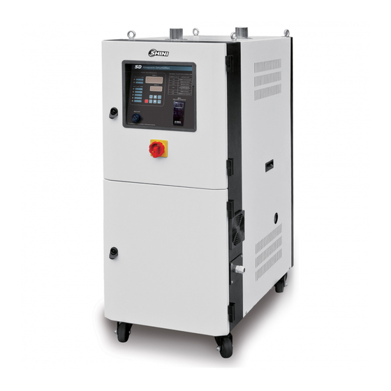
- Page 1 SD-H Series Honeycomb Dehumidifiers Date: Sep. 2014 Version: Ver.D (English)
-
Page 3: Table Of Contents
Contents General Description ..................9 1.1 Coding Principle ..................10 1.2 Feature....................10 1.3 Technical Specifications................ 12 1.3.1 Specifications ................12 1.3.2 Durline Drawing ................13 1.3.3 Drying Capacity ................14 1.4 Safety Regulations ................15 1.4.1 Safety Signs and Labels .............. 15 1.4.2 Signs and Labels ................. - Page 4 2.6.12 Honeycomb ................38 2.6.13 Parts List of Honeycomb (SD-700H/1000H/2000H/3000H)... 40 2.7 Main Electrical Components Description..........43 2.8 Operation Procedures ................44 2.8.1 Operation Regulations..............44 2.8.2 Description of Touch Screen ............45 2.8.3 Touch Panel Appear Error ............45 2.8.4 Dew-point Monitor ...............
- Page 5 Trouble-shooting ..................77 Maintenance and Repair ................79 6.1 Honeycomb................... 80 6.2 Filter ...................... 80 6.3 Cooler ....................81 6.4 Clean of Y type strainer................. 82 6.5 Maintenance Schedule................82 6.5.1 General Machine Information ............82 6.5.2 Check After Installation..............82 6.5.3 Daily Checking................
- Page 6 Table 2-16:Adjustment of Differential Time (D) ..........51 Table 2-17:System Alarm Information List ............. 53 Table 4-1:Control Panel Table ............... 66 Table 4-2:Wrong Codes Remark..............73 Picture Index Picture 1-1:Durline Drawing ................13 Picture 1-2:Safety Signs and Labels .............. 15 Picture 1-3:Safety Regulations for the Blowers..........
- Page 7 Picture 2-25:Time Setting 2................52 Picture 2-26:Alarm Fault Records ..............52 Picture 2-27:Help Menu ................. 53 Picture 2-28:Help Menu ................. 55 Picture 2-29:Embedded Dew-point Monitor ........... 56 Picture 2-30:Portable Dew-point Monitor ............56 Picture 2-31:Oil Filter ..................57 Picture 3-1:Honeycomb Rotor................ 60 Picture 3-2:Installation of the Rotor (SD-40H~700H) ........
- Page 8 8(83)
-
Page 9: General Description
Please read through this operation manual before using the machine to prevent damages of the machine or personal injuries. SD-H series honeycomb dehumidifiers are mainly used to dry hygroscopic engineering plastics. A honeycomb-rotor is used to offer effective drying, which under ideal conditions, can supply dehumidified dry air with a dew-point lower than -40℃.This series comprises 13 models of honeycomb dehumidifiers, the... -
Page 10: Coding Principle
● Adopts P.I.D. temperature controller to accurately control regenerative temperature. ● The dehumidifying system of the SD-H series features two coolers to ensure a low return air temperature and low dew-point. ● Return air filter is mounted inside to ensure no contamination to the honeycomb. - Page 11 Chapter 6, which contains service instructions intended for service engineers. Other chapters contain instructions for the daily operator. Any modifications of the machine must be approved by SHINI in order to avoid personal injury and damage to machine. We shall not be liable for any damage caused by unauthorized change of the machine.
-
Page 12: Technical Specifications
1.3 Technical Specifications 1.3.1 Specifications Table 1-1:Specifications Model 120H 200H 400H 700H 1000H 1500H 2000H 3000H 4000H Regen. Heater (kW) Regen. Blower 0.2 / 0.2 / 0.2 / 0.4 / 0.75 / 1.5 / 2.4 / 5.5 / 5.5 / 5.5×2 / (kW,50 / 60Hz) 6.3×2... -
Page 13: Durline Drawing
1.3.2 Durline Drawing SD-40H~700H SD-1000H~2000H SD-3000H~4000H Picture 1-1:Durline Drawing 13(83) -
Page 14: Drying Capacity
1.3.3 Drying Capacity Table 1-2:Specifications Moisture Moisture Drying capacity (kg/hr) Specific Material Drying Content Content Time Heat Specific Material temp. Before After (hr) (J/kg.℃) Gravity (℃) Drying Drying (kg/dm 120H 200H 400H 700H 1000H 1500H 2000H 3000H 4000H 0.34 0.02 1065 1500 1600... -
Page 15: Safety Regulations
1.4 Safety Regulations Note! Electrical installation of the machine should be done by qualified electricians. Before connect through power supply, make sure that power switch specifications and security ratings are suitable and reliable, and also the main switch is turned to OFF. Turn off main switch and auto-start switch before service and maintenance. -
Page 16: Signs And Labels
Water outlet: drainage outlet. 1.4.3 Transportation and Storage of the Machine Transportation 1) SD-H series honeycomb dehumidifiers are packed in crates or plywood cases with wooden pallet at the bottom, suitable for quick positioning by fork lift. 2) After unpacked, castors equipped on the machine can be used for ease of movement. -
Page 17: Safety Regulations For The Blowers
4) This equipment works normally in the environment with altitude within 3000m. 5) At least a clearance of 1m surrounding the equipment is required during operation. Keep this equipment away from flammable sources at least two meters. 6) Avoid vibration, magnetic disturbance at the operation area. Rejected parts disposal When the equipment has run out its life time and can not be used any more, unplug the power supply and dispose of it properly according to local code. -
Page 18: Exemption Clause
Shini (including employees and agents). Shini is exempted from liability for any costs, fees, claims and losses caused by reasons below: 1. Any careless or man-made installations, operation and maintenances upon machines without referring to the Manual prior to machine using. -
Page 19: Structure Characteristics And Working Principle
2. Structure Characteristics and Working Principle 2.1 Working Principle The moisture contained in the air which is waited for treating) will be absorbed by hygroscopic materials, hereafter, be de-absorbed by the regenerated hot air. And the two airstream work together in the rotation wheel. So, with the rotation of the wheel, moisture will be absorbed and de-absorbed continuously, and drain out via de-absorbing by regenerated air to form a steady low dew point airstream for using. -
Page 20: Working Principle Illustration
2.4 Working Principle Illustration Hopper Dryer Electrical Heat Regen. Heater for Drying Honeycomb Rotor Regen. Filter Cooler Regen. Blower Drying Blower Cooler Every working area of honeycomb rotor Process Filter 1) Dehumidifying zone 2) Regenerative zone 3) Cooling zone Picture 2-1:Working Principle Illustration 2.5 Dew-point Comparison Picture 2-2:Dew-point Comparison 20(83) -
Page 21: Drawing And Parts List
2.6 Drawing and Parts List Structural Drawing 2.6.1 Parts name: 1. Control panel 2. Main switch 3. Lock 4. Air inlet 5. Air outlet 6. Wet air outlet 7. Cooling window 8. Castor Picture 2-3:Structural Drawing (SD-40H~700H) 21(83) -
Page 22: Picture 2-4:Structural Drawing (Sd-1000H~4000H)
Parts name: 1. Right lower door 2. Right upper door 3. Right front door 4. Cooler 5. Air inlet pipe 6. Heating case components 7. Return air pipe 8. Filter component cabinet 9. Circulation filter barrel lid 10. Circulation filter barrel flange 11. -
Page 23: Assembly Drawing (Sd-40H~700H)
2.6.2 Assembly Drawing (SD-40H~700H) Remarks: Please refer to material list 2.6.3 for specific explanation of the Arabic numbers in parts drawing. Picture 2-5:Assembly Drawing (SD-40H~700H) 23(83) -
Page 24: Parts List (Sd-40H~700H)
2.6.3 Parts List (SD-40H~700H) Table 2-1:Parts List (SD-40H~80H) Part No. Description SD-40H SD-80H Upper door Short bolt door lock YW00816100000 YW00816100000 Control panel YR40000400500 YR40000400500 Main switch* YE10200300000 YE10200300000 Lower door Cross-head nut YW09675100000 YW09675100000 Filtering bucket lid YL21000300000 YL21000300000 Filter** YR50128300000 YR50128300000... - Page 25 Part No. Description SD-40H SD-80H Honey comb lower lid BA40508000010 BA40508000010 Side middle beam Synchronized belt** YR00202500000 YR00202500000 Motor YM50102600000 YM50102600000 Front middle beam Exhausting fan** YM60121200400 YM60121200400 * means possible broken parts. ** means easy broken part. and spare backup is suggested. Please confirm the version of manual before placing the purchase order to guarantee that the item number of the spare part is in accordance with the real object.
-
Page 26: Table 2-2:Parts List (Sd-120H~200H)
Table 2-2:Parts List (SD-120H~200H) Part No. Description SD-120H SD-200H Upper door Short bolt door lock YW00816100000 YW00816100000 Control panel YR40000400500 YR40000400500 Main switch* YE10200300000 YE10210300000 Lower door Cross-head nut YW09675100000 YW09675100000 Filtering bucket lid YL21000300000 YL21000300000 Filter** YR50708000100 YR50203000000 Control box Hinge YW06203100200 YW06203100200... - Page 27 Part No. Description SD-120H SD-200H Synchronized belt** YR00202500000 YR00203400000 Motor YM50102600000 YM50102600000 Front middle beam Exhausting fan** YM60121200400 YM60121200400 * means possible broken parts. ** means easy broken part. and spare backup is suggested. Please confirm the version of manual before placing the purchase order to guarantee that the item number of the spare part is in accordance with the real object.
-
Page 28: Table 2-3:Parts List (Sd-400H~700H)
Table 2-3:Parts List (SD-400H~700H) Part No. Description SD-400H SD-700H Upper door Short bolt door lock YW00816100000 YW00816100000 Control panel YR40000400500 YR40000400500 Main switch* YE10220300000 YE40635000000 Lower door Cross-head nut YW09675100000 YW09675100000 Filtering bucket lid YL21000300000 YL21000300000 Filter** YR50241400100 YR5024140000 Control box BH33040000250 Hinge YW06203100200... - Page 29 Part No. Description SD-400H SD-700H Side middle beam Synchronized belt** YR00304700000 YR00305800000 Motor YM50512600000 YM50512600000 Front middle beam Exhausting fan** YM60121200400 YM60121200400 * means possible broken parts. ** means easy broken part. and spare backup is suggested. Please confirm the version of manual before placing the purchase order to guarantee that the item number of the spare part is in accordance with the real object.
-
Page 30: Assembly Drawing (Sd-1000H)
2.6.4 Assembly Drawing (SD-1000H) Remarks: Please refer to material list 2.6.5 for specific explanation of the Arabic numbers in parts drawing. Picture 2-6:Assembly Drawing (SD-1000H) 30(83) -
Page 31: Parts List (Sd-1000H)
2.6.5 Parts List (SD-1000H) Table 2-4:Parts List (SD-1000H) 序号 名称 物料编号 Rack metal plate Filter ** YR50241400100 Filter fastener YR10026000000 Honeycomb assembly Filter ** YR50203000000 Filter fastener YR10026000100 Drying blower * YM30150300300 Regeneration blower * BM30053500050 Mobile castor YW03000400200 Castor with break YW03000400000 Cooler BL03100049220... -
Page 32: Assembly Drawing (Sd-1500H)
2.6.6 Assembly Drawing (SD-1500H) Remarks: Please refer to material list 2.6.7 for specific explanation of the Arabic numbers in parts drawing. Picture 2-7:Assembly Drawing (SD-1500H) 32(83) -
Page 33: Parts List (Sd-1500H)
2.6.7 Parts List (SD-1500H) Table 2-5:Parts List (SD-1500H) Description Part No. Description Part No. Front plate left Water flow regulator Right lower door Return air pipe Right upper door Rear plate Star nut YW09675100000 Return air pipe Vacuum hopper cover 12l YL21001200100 Air outlet pipe Honeycomb... -
Page 34: Assembly Drawing (Sd-3000H)
2.6.8 Assembly Drawing (SD-3000H) Remarks: Please refer to material list 2.6.9 for specific explanation of the Arabic numbers in parts drawing. Picture 2-8:Assembly Drawing (SD-3000H) 34(83) -
Page 35: Parts List (Sd-3000H)
2.6.9 Parts List (SD-3000H) Table 2-6:Parts List (SD-3000H) Description Part No. Description Part No. Front plate left Water flow regulator Right lower door Return air pipe Right upper door Rear plate Star nut YW09675100000 Return air pipe Vacuum hopper cover 12l YL21001200100 Air outlet pipe Honeycomb... -
Page 36: Pipe Heaters
2.6.10 Pipe Heaters Parts name: 1. Electric wood cover 2. Pipe heater 3. Heater wrapper sheet 1 4. Heating tank 5. Heater cover plate 6. Heater wrapper sheet 2 7. Heater fixed seat Picture 2-9:Pipe Heaters 36(83) -
Page 37: Heating Case
2.6.11 Heating Case Picture 2-10:Heating Case Table 2-7:Optional heating case spare parts list (SD-200H~700H-PHC) Part No. Description SD-200H SD-400H SD-700H Heating case Pipe heater BH70124000550 BH70184000550 BH70244000850 Heating case cover Table 2-8:Heating case spare parts list (SD-1000H~3000H) Part No. Description SD-1000H SD-1500H SD-2000H... -
Page 38: Honeycomb
2.6.12 Honeycomb Picture 2-11:Honeycomb Parts Drawing (SD-700H/1000H/2000H) 38(83) -
Page 39: Picture 2-12:Honeycomb Parts Drawing(Sd-1500H)
Picture 2-12:Honeycomb Parts Drawing(SD-1500H) Picture 2-13:Honeycomb Parts Drawing (SD-3000H) 39(83) -
Page 40: Parts List Of Honeycomb (Sd-700H/1000H/2000H/3000H)
2.6.13 Parts List of Honeycomb (SD-700H/1000H/2000H/3000H) Table 2-9:Parts List (SD-700H) Description Part No. Description Part No. 4” Honeycom Flat washer 16 flange 2.5” honeycomb Spring YW01201800000 flange Lower cover Hex nut M16 Hexgon socket head Honeycomb shaft cap screw M8 Sychronous belt YR00305800000 Gear motor... -
Page 41: Table 2-11:Parts List (Sd-1500H)
Table 2-11:Parts List (SD-1500H) Description Part No. Description Part No. Hexgon socket head cap screw YW61082000000 Honeycomb shaft M8×20 Fixed honeycomb Honeycomb support Honeycomb YW71773000100 Hexgon socket head Roller chain YW09085100000 YW61061000100 cap screw M6×10 Driven sprocket Flat washer 16 YW66163000000 Gear motor YM10916000000... -
Page 42: Table 2-12:Parts List (Sd-3000H)
Table 2-12:Parts List (SD-3000H) Description Part No. Description Part No. Cleading Shaft coupler YW90263700000 Hexgon socket head cap screw YW61061000100 Tensioner M6×10 Hexgon socket head cap screw YW61083500000 Motor cabinet M8×35 Flat gasket 8×19 YW66081900000 Drive sprocket Honeycomb frame Bearing Nut M16 YW61083500000 Bearing... -
Page 43: Main Electrical Components Description
2.7 Main Electrical Components Description Overload Relay At delivery, the overload relay is set for manual reset. (The reset button pointing to H). Manually reset the relay at the tripping of the switch. When motor overload occurs, stop the machine, then check and solve the problem. After that open the door of control box, press down the reset button of overload relay (if you can not press down the reset button, wait for one minute.) ⑥... -
Page 44: Operation Procedures
2.8 Operation Procedures Before connecting electrical power source, the main power switch must be turned to OFF position. After the machine connected with power source, turn the main power switch to ON position. According to your applications, operate drying and loading system respectively. 2.8.1 Operation Regulations Picture 2-15:Operation Regulations 1) Do not use keen-edged object instead of hands to operate the touch screen,... -
Page 45: Description Of Touch Screen
2.8.2 Description of Touch Screen Picture 2-16:Description of Touch Screen A:Display B:Touch panel C:LED status indicator 2.8.3 Touch Panel Appear Error Table 2-13:Touch Panel Information XBT GT State indicator light Green (light) Work welled Orange (light) Backlight lamp burning Orange (shine) During software startup Red (light) Power status... -
Page 46: Picture 2-17:Screen Operation Flow Table
Picture 2-17:Screen Operation Flow Table 4. Explanation of the Menus 1) Initial menu When the system is connected with power source, the initial default screen will display as shown below. Touch the button of "English" or "Chinese" to select either English or Chinese languages to login "Drying Process" screen. Picture 2-18:System Default System 46(83) -
Page 47: Picture 2-19:Drying Process Screen
2) Drying process menu. Drying process menu is as shown below: Picture 2-19:Drying Process Screen A. Operation of the menu Start the system: Touch the start switch to make it show ON, then the system starts. Stop the system: Touch the start switch again to make it show OFF, then the system stops running. -
Page 48: Picture 2-20:Temperature Parameters Setting 1
3) Temperature parameters menu Touch parameter setting button at the right side of Conveying Proccess Screen. Then, the system will pop out a password window for inputing user name: Shini, and passwords 3588. Press "ENTER" button to confirm. By then, the numeric keypad will turn off and return to the password window. -
Page 49: Picture 2-21:Temperature Parameters Setting 2
missing, then the operator won't be able to log into the system parameter setup screen. It is better to preserve this password either by system administrator or senior operator. After input correct password, the screen will show the following "temperature parameter setting"... -
Page 50: Picture 2-23:Process Temp. Parameters Setting 2
"ENTER" to confirm the new parameter. Picture 2-23:Process temp. Parameters Setting 2 The max. and min. display area of the numeric keypad shows the present max. and min. setting value. If the setting value exceeds the limits, it would be invalid to press "ENTER". -
Page 51: Picture 2-24:Time Setting
Adjustment of Differential Time (D) Table 2-16:Adjustment of Differential Time (D) 4) Time Setting A. Touch the "Time Setting" button to enter into Time Setting screen as shown below: Picture 2-24:Time Setting Note! After setting the auto-start time, the button OFF will be on. By then, the machine will run according to the set time. -
Page 52: Picture 2-25:Time Setting 2
Picture 2-25:Time Setting 2 After touching any parameter setting menu, a numeric keypad will appear. Input each parameter and then press “SET”. Then, the new setting comes into effect. The setting can be cancelled by pressing “cancel”. 5) Alarm Fault Records Touch "Alarm Display"... -
Page 53: Picture 2-27:Help Menu
Picture 2-27:Help Menu 1. When alarm fault records cover more than displaying space, touch "Up" or "Down" keys to read more records. 2. According to the alarm information, the operator could get the troubleshooting information from the instruction book. 3. Press "EXIT" button to exit from this screen. 4. - Page 54 Alarm message Results Possible reasons Thermocouple is not connected or Regeneration Dryer and dehumidifier stop working, poor connection or wrongly thermocouple break and flickering of red alarm light. connected. Thermocouple is not connected or Return air thermocouple Dryer and dehumidifier stop working, poor connection or wrongly break and flickering of red alarm light.
-
Page 55: Picture 2-28:Help Menu
6) Help menu Touch "Help" button at the right side of Drying Proocess or Conveying Process screen to enter into system help menu screen. Touch the menu button to get corresponding help message. Picture 2-28:Help Menu 55(83) -
Page 56: Dew-Point Monitor
2.8.4 Dew-point Monitor 1. Embedded Dew-point Monitor Picture 2-29:Embedded Dew-point Monitor 2. Portable Dew-point Monitor Picture 2-30:Portable Dew-point Monitor 56(83) -
Page 57: Oil Filter
2.8.5 Oil Filter EOF-1000~4000 EOF-30~500 Picture 2-31:Oil Filter Type Applicable Model EOF-30 SD-40H~120H EOF-150 SD-150H/200H EOF-300 SD-300H/400H EOF-500 SD-700H EOF-1000 SD-1000H EOF-1500 SD-1500H EOF-2000 SD-2000H EOF-3000 SD-3000H EOF-4000 SD-4000H 1. Selection Aim: There is much oil in dehumidifying air return, oil filter is selected to ensure dehumidifying function and prolong service life of honeycomb. - Page 58 2. Filter cleaning steps of EOP-30~500: 1) Open snap hook 4, take out tank cover 1, stainless steel filter 2 and activated carbon filter 3. 2) Loose butterfly nut, take out stainless steel filter 2, and remove away dust and oil from it by pressured air. 3) Loose butterfly nut, take out activated carbon filter 3 and replace activated carbon.
-
Page 59: Installation Testing
Installation Testing Read this chapter carefully before installation. Install the machine by following steps. Power supply of the machine should be handled by qualified electricians! Notes! Keep the machine 2m from the combustible distance. 3.1 Attention 1) Make sure voltage and frequency of the power source comply with those indicated on the manufacturer nameplate, which is attached to the machine. -
Page 60: Honeycomb-Rotor
3.2 Honeycomb-rotor 3.2.1 What is Honeycomb-rotor? The main body of the honeycomb-rotor is a honeycomb, made by ceramic fibre and organic additives, sintered under high temperature with molecular sieve and silica gel, to be strongly bonded together and form a solid and hard surface. Not like common molecular sieve, which will produce dusts and fines to pollute raw materials when aging or become saturated requiring regular replacement, honeycomb-rotor offer unlimited long life and can be cleaned when it is polluted. -
Page 61: Installation Of The Rotor (Sd-40H~700H)
3.2.2 Installation of the Rotor (SD-40H~700H) Picture 3-2:Installation of the Rotor (SD-40H~700H) 1) The upper and lower lid of honey-comb should install Teflon gasket (Fig. 1). 2) Use 4 screws to fix the rotor base on the machine frame firmly, and then install the shaft accordingly (Fig. -
Page 62: Installation Of The Rotor (Sd-1000H~4000H)
3.2.3 Installation of the Rotor (SD-1000H~4000H) Picture 3-3:Installation of the Rotor (SD-1000H~4000H) 1) Use one solid strap or applicable washer to lifted or block up to the wheel 3 to align the wheel bearing bore and fixed honeycomb lid 2 center hole. 2) Use honeycomb shaft 16 to penetrate the wheel 3 and fixed honeycomb lid 2, and install synchronic belt 4 on the rotor 3. -
Page 63: Heater Assemblies
3.3 Heater Assemblies 1) Install the heating pipe in the heater. 2) Fix the heater into the housing. (See right picture) Warning! Hot surfaces could burn hands. Take care of high temperature! This label should be stick to the shell of heater. Picture 3-4:Heater Assemblies 3.4 EGO The EGO value has been setting before out factory, Don't modify it. -
Page 64: Cyclone Dust Collector
3.5 Cyclone Dust Collector Picture 3-6:Installation Diagram of Cyclone Dust Collector Cyclone Dust Collector Installation steps: 1. Connect 1 and 5 with a heat-resistant duct and fixed both the ends with stainless steel tube. 2. Connect 2 and 3 with a heat-resistant duct and fixed both the ends with stainless steel tube. -
Page 65: Plate Heat Exchanger
Oil filter installation steps: 1. Screw the oil filter on the top plate of the honeycomb dehumidifier. 2. Connect 1 and 2 with a heat-resistant duct and fixed both the ends with stainless steel tube. 3. Connect 3 and 4 with a heat-resistant duct and fixed both the ends with stainless steel tube. -
Page 66: Operation
4. Operation 4.1 Control Panel Picture 4-1:Control Panel Table 4-1:Control Panel Table Name Function description Remarks Green light on indicates working Indicates the working status of status Running indicating blower and heater Green light off indicates stop status Fault indicating Indicates current alarm message Red light on indicates fault occurs Set weekly start or intermittent... -
Page 67: Panel Operation
4.2 Panel Operation 1) Open the main switch. 2) Press "RUN/STOP "key to start loading. 4.3 Temperature Setup 1) The setup number will flicker after pressing "SET" key, add or decrease temperature by pressing key. 2) Press "ENTER" key to confirm the input value. 4.4 PID Auto-tuning Setting 1) Press “SET”... -
Page 68: Weekly Time Start Setup
2) PV displays "0-ON" to stand for drying periods. "0-OFF" stands for machine stop time. Press key to add or decrease time value of "SV/setup value". Each press of can add or decrease 15 mins set time. 3) Press "ENTER" to confirm the input time value and enter into "0-OFF" time setup items, then repeat step 2. -
Page 69: Picture 4-5:Weekly Time Start Setup 1
Picture 4-5:Weekly Time Start Setup 1 2) Press key to add or decrease the time value in "SV/setup value " from "1-OFF" . Press "ENTER" to confirm the input value and comes into the time setup items of "2-ON""TUE-ON". Picture 4-6:Weekly Time Start Setup 2 3) Do the same setup again and again to setup the ON/OFF time from Monday to Sunday. -
Page 70: Picture 4-8:Weekly Time Start Setup 4
1. F-20 functions as an password lock,hold on"SET"till the"PV"displays F-20. 2. Press key and only after input 0021 in the SV,can you press "ENTER"to come into F-03 and other settings,so F-20 functions as an passwordlock for entering into next parameters setup, which prevents the modification from unprofessionals. -
Page 71: Present Time Modification
4.7 Present Time Modification 1) Repeat the above steps until PV displays "TIME" to stand for present time. 2) Press key to add or decrease time. 3) Press "ENTER" key and PV displays "DAY" to stand for week days. 4) Press key to add or decrease days. - Page 72 can alter value, press “ENTER” to input after confirming 3) Now pressing then jump to F-07. 4) If you want to leave the function setting, just press “SET”. 1. F-06 stands for the passwords of second level. 2. F-07 stands for proportional band of heating side (P); it is a preset value before delivery.
-
Page 73: Wrong Codes Remark
4.11 Wrong Codes Remark Table 4-2:Wrong Codes Remark Wrong codes Remark E-01 Break of temperature-sensed line E-02 Inverse phase E-03 Overload input E-04 Overheat input for regen. EGO E-05 Maximum temperature protection E-07 Thermal protection temperature E-08 Memory errors E-09 Rotor Microswitch input E-11 Reversed-phase of temperature sensed line... -
Page 74: Picture 4-11:Parts Of Dew-Point Monitor
Copper joint, installation seat for dew-point monitor Picture 4-11:Parts of Dew-point Monitor 3) Dismantle the copper joint of original machine and replace it with installation seat for dew-point monitor. Then dismantle straight form bushing from copper joint of original machine and install it on the installation seat, and connect copper pipe with straight form bushing. -
Page 75: Picture 4-14:Installation For Transmitter
4) Install dew-point transmitter assembly to copper joint. Picture 4-14:Installation for Transmitter 5) Connect signal wire. Particular shape of signal wire joint would avoid the wrong insert and connection. Picture 4-15:Connection of Signal Wire 6) Match dew-point monitor with holes on the panel and fix the installation. Picture 4-16:Installation for Dew-point Monitor 75(83) -
Page 76: Picture 4-17:Connection Of Dew-Point Monitor
7) Connect signal wires of the transmitter and power lines of dew-point monitor with the according terminals. Connet contact No.1 and No.2 with power, supply is 220VAC. Contact No.3, No.4 and No.5 are idle. Connect contact No.6, No.7 and No.8 with the signal of transmitter. (C- Connects contact No.6, C+ connects contact No.7 and wire No.9 connects contact No.8. -
Page 77: Trouble-Shooting
Trouble-shooting Troubles Possible causes Solutions 1. Does not connect through 1. Connect through power supply. power supply. 2. Main power switch 2. Replace main power switch. Main power indicator breakdown. does not light after turn 3. Problems of electrical wires. 3. - Page 78 Troubles Possible causes Solutions 1. Problems of rotor motor. 1. Check or replace the motor. 2. Rotor belt broken. 2. Replace the belt. E-09 is shown at PV, 3. Problems of electrical circuit. 3. Check the electrical circuit. buzzer sounds and 4.
-
Page 79: Maintenance And Repair
Maintenance and Repair Note! 1) Turn off the main switch and control switch and unplug the cord from power supply before service and maintenance. 2) Be sure not to modify electrical wiring or reassemble the electrical components inside of the control box. 3) Always refer to the electrical diagram of this manual to check and maintain the electrical wiring problems. -
Page 80: Honeycomb
6.1 Honeycomb Honeycomb Rotor cleaning steps: 1) Use a vacuum-cleaner with brush to suck up the dust on rotor surface. 2) Blow off the dust in the rotor channels with compressed air. 3) If there is dirt sticking to the channel walls inside the rotor, cleaning steps as follows: a. -
Page 81: Cooler
2) Blow off the dust on the air filter screen and the cover with pressure air. 3) Wipe off the barrel wall of air filter with dishcloth. 4) After cleaning, place all parts in reversed order carefully. Picture 6-1:Filter Note! Do not let any impurities fall into filter container. -
Page 82: Clean Of Y Type Strainer
6.4 Clean of Y type strainer The cleaning work should be done according to the condition of cooling water dust. Clean it in time in such situations, such as hot air and insufficient cooling water flow. 6.5 Maintenance Schedule 6.5.1 General Machine Information Model Manufacture date Ф... -
Page 83: Monthly Checking
Check whether air pipe is shed, leaked and loose. 6.5.5 Monthly Checking Check if the transmission belt is loose or not. Check the performance of gear motor. Check if there are leakages in honeycomb-rotor. 6.5.6 Half-yearly Checking Check if there are damages of heat-resistant hoses. Check the pipe heaters.
Need help?
Do you have a question about the SD-H Series and is the answer not in the manual?
Questions and answers