Sign In
Upload
Manuals
Brands
Shini Manuals
Dehumidifier
SD-1000H
Shini SD-1000H Manuals
Manuals and User Guides for Shini SD-1000H. We have
3
Shini SD-1000H manuals available for free PDF download: Operation Manual, Manual
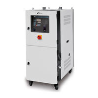
Shini SD-1000H Operation Manual (83 pages)
Honeycomb
Brand:
Shini
| Category:
Dehumidifier
| Size: 2 MB
Table of Contents
Table of Contents
3
1 General Description
9
Coding Principle
10
Feature
10
Technical Specifications
12
Specifications
12
Durline Drawing
13
Picture 1-1:Durline Drawing
13
Drying Capacity
14
Safety Regulations
15
Safety Signs and Labels
15
Picture 1-2:Safety Signs and Labels
15
Signs and Labels
16
Transportation and Storage of the Machine
16
Safety Regulations for the Blowers
17
Exemption Clause
18
Picture 1-3:Safety Regulations for the Blowers
18
2 Structure Characteristics and Working Principle
19
Working Principle
19
Relative Humidity and Dew-Point
19
Why Choose SD-H
19
Working Principle Illustration
20
Dew-Point Comparison
20
Picture 2-1:Working Principle Illustration
20
Picture 2-2:Dew-Point Comparison
20
Drawing and Parts List
21
Structural Drawing
21
Picture 2-3:Structural Drawing (SD-40H~700H)
21
Picture 2-4:Structural Drawing (SD-1000H~4000H)
22
Assembly Drawing (SD-40H~700H)
23
Picture 2-5:Assembly Drawing (SD-40H~700H)
23
Parts List (SD-40H~700H)
24
Table 2-2:Parts List (SD-120H~200H)
26
Table 2-3:Parts List (SD-400H~700H)
28
Assembly Drawing (SD-1000H)
30
Picture 2-6:Assembly Drawing (SD-1000H)
30
Parts List (SD-1000H)
31
Assembly Drawing (SD-1500H)
32
Picture 2-7:Assembly Drawing (SD-1500H)
32
Parts List (SD-1500H)
33
Assembly Drawing (SD-3000H)
34
Picture 2-8:Assembly Drawing (SD-3000H)
34
Parts List (SD-3000H)
35
Pipe Heaters
36
Picture 2-9:Pipe Heaters
36
Heating Case
37
Picture 2-10:Heating Case
37
Honeycomb
38
Picture 2-11:Honeycomb Parts Drawing (SD-700H/1000H/2000H)
38
Picture 2-12:Honeycomb Parts Drawing(SD-1500H)
39
Picture 2-13:Honeycomb Parts Drawing (SD-3000H)
39
Parts List of Honeycomb (SD-700H/1000H/2000H/3000H)
40
Table 2-11:Parts List (SD-1500H)
41
Table 2-12:Parts List (SD-3000H)
42
Main Electrical Components Description
43
Picture 2-14:Overload Relay
43
Operation Procedures
44
Operation Regulations
44
Picture 2-15:Operation Regulations
44
Description of Touch Screen
45
Touch Panel Appear Error
45
Picture 2-16:Description of Touch Screen
45
Picture 2-17:Screen Operation Flow Table
46
Picture 2-18:System Default System
46
Picture 2-19:Drying Process Screen
47
Picture 2-20:Temperature Parameters Setting 1
48
Picture 2-21:Temperature Parameters Setting 2
49
Picture 2-22:Process Temp. Parameters Setting 1
49
Picture 2-23:Process Temp. Parameters Setting 2
50
Table 2-14:Adjustment of Proportion (P)
50
Picture 2-24:Time Setting
51
Table 2-16:Adjustment of Differential Time (D)
51
Picture 2-25:Time Setting 2
52
Picture 2-26:Alarm Fault Records
52
Picture 2-27:Help Menu
53
Table 2-17:System Alarm Information List
53
Picture 2-28:Help Menu
55
Dew-Point Monitor
56
Picture 2-29:Embedded Dew-Point Monitor
56
Picture 2-30:Portable Dew-Point Monitor
56
Oil Filter
57
Picture 2-31:Oil Filter
57
3 Installation Testing
59
Attention
59
Honeycomb-Rotor
60
What Is Honeycomb-Rotor
60
Picture 3-1:Honeycomb Rotor
60
Installation of the Rotor (SD-40H~700H)
61
Picture 3-2:Installation of the Rotor (SD-40H~700H)
61
Installation of the Rotor (SD-1000H~4000H)
62
Picture 3-3:Installation of the Rotor (SD-1000H~4000H)
62
Heater Assemblies
63
Ego
63
Picture 3-4:Heater Assemblies
63
Picture 3-5:EGO
63
Cyclone Dust Collector
64
Oil Filter
64
Picture 3-6:Installation Diagram of Cyclone Dust Collector
64
Picture 3-7:Installation Diagram of Oil Filter
64
Plate Heat Exchanger
65
Picture 3-8:Plate Heat Exchanger over Figure
65
4 Operation
66
Control Panel
66
Picture 4-1:Control Panel
66
Panel Operation
67
Temperature Setup
67
PID Auto-Tuning Setting
67
Intermittent Running Setup
67
Picture 4-2:Intermittent Running Setup 1
67
Weekly Time Start Setup
68
Picture 4-3:Intermittent Running Setup 2
68
Picture 4-4:Intermittent Running Setup 3
68
Picture 4-5:Weekly Time Start Setup 1
69
Picture 4-6:Weekly Time Start Setup 2
69
Picture 4-7:Weekly Time Start Setup 3
69
Picture 4-8:Weekly Time Start Setup 4
70
Picture 4-9:Weekly Time Start Setup 5
70
Present Time Modification
71
Weekly Time Start
71
Lock Setup Way
71
The Second Level of Advanced Setting
71
Wrong Codes Remark
73
Installation for Dewpoint Monitor
73
Picture 4-10:Hole Site
73
Picture 4-11:Parts of Dew-Point Monitor
74
Picture 4-12:Copper Joint Assembly of Original Machine
74
Picture 4-13:Installation Seat
74
Picture 4-14:Installation for Transmitter
75
Picture 4-15:Connection of Signal Wire
75
Picture 4-16:Installation for Dew-Point Monitor
75
Picture 4-17:Connection of Dew-Point Monitor
76
5 Trouble-Shooting
77
6 Maintenance and Repair
79
Honeycomb
80
Filter
80
Cooler
81
Picture 6-1:Filter
81
Clean of y Type Strainer
82
Maintenance Schedule
82
General Machine Information
82
Check after Installation
82
Daily Checking
82
Weekly Checking
82
Monthly Checking
83
Half-Yearly Checking
83
Yearly Checking
83
Year Checking
83
Advertisement
Shini SD-1000H Manual (50 pages)
Honeycomb Dehumidifiers
Brand:
Shini
| Category:
Dehumidifier
| Size: 3 MB
Table of Contents
Table of Contents
3
General Description
7
Coding Principle
8
Feature
8
Technical Specifications
9
Durline Drawing
9
Specifications
9
Picture 1-1: Durline Drawing
9
Drying Capacity
10
Safety Regulations
11
Safety Signs and Labels
11
Signs and Labels
11
Transportation and Storage of the Machine
12
Safety Regulations for the Blowers
13
Picture 1-2: Safety Regulations for the Blowers
13
Exemption Clause
14
Structure Characteristics and Working Principle
15
Working Principle
15
Relative Humidity and Dew-Point
15
Picture 2-1: Working Principle Illustration
15
Why Choose SD-H
16
Options
17
Installation Testing
19
Machine Location
19
Power Connectors
19
Picture 3-1: Installation Drawing
19
Water Connections
20
Cooling Water Connection
20
Picture 3-2: Cooling Water Connection
20
Condensation Drainage Pipe
21
Cyclone Dust Collector
22
Oil Filter
22
Picture 3-3: Installation Diagram of Cyclone Dust Collector
22
Picture 3-4: Installation Diagram of Oil Filter
22
Plate Heat Exchanger
23
Picture 3-5: Plate Heat Exchanger over Figure
23
Operation
24
Operation Procedure for HMI
24
Description of Touch Screen
24
Touch Panel Appear Error
24
Picture 4-1: Description of Touch Screen
24
Screen Operation Flow Table
25
Menu Particular
25
System Default Screen
25
Picture 4-2: Screen Operation Flow Table
25
Picture 4-3: System Initial Screen
25
Dehumidifying Process
26
Password Unlock
26
Picture 4-4: Dehumidifying Process Screen
26
Picture 4-5: Password Input Screen
26
Picture 4-6: Drying Process
27
Picture 4-7: Parameter Setting Menu Screen
27
Picture 4-8: Time Setting Screen
28
Picture 4-9: Parameter Setting
28
Working Modes of Regeneration Heater (Dehumidifying Function)
29
Picture 4-10: Parameter Setting Screen
29
Picture 4-11: Drying Process Screen
29
Picture 4-12: Dehumidify Process Screen
30
Picture 4-13: Parameter Setting Screen
30
Picture 4-14: Drying Process Screen
31
Picture 4-15: Dehumidify Process Screen
31
Working Modes of Material Drying
32
Picture 4-16: Drying Process Screen
32
Picture 4-17: Drying Process Screen
32
Picture 4-18: Recipe Setting Screen
33
Picture 4-19: Drying Process Screen
33
Alarms Fault Records
34
Picture 4-20: Drying Process Screen
34
Picture 4-21: Alarm Fault Records
34
Trouble-Shooting
36
Maintenance and Repair
38
The Useful Life of the Key Parts of the Product
39
Filter
39
Picture 6-1: Filter
39
Honeycomb-Rotor
40
What Is Honeycomb-Rotor
40
Installation of the Rotor (SD-40H~700H)
40
Picture 6-2: Honeycomb Rotor
40
Picture 6-3: Installation of the Rotor (SD-40H~700H)
40
Installation of the Rotor (SD-1000H~4000H)
41
Picture 6-4: Installation of the Rotor (SD-1000H~4000H)
41
Honeycomb Cleaning Steps
42
Cooler
43
Ego
44
Oil Filter Cleaning
44
Picture 6-5: EGO
44
Picture 6-6: Oil Filter
44
Installation for Dewpoint Monitor(Option)
45
Picture 6-7: Hole Site
45
Picture 6-8: Parts of Dew-Point Monitor
46
Picture 6-9: Copper Joint Assembly of Original Machine
46
Picture 6-10: Installation Seat
46
Picture 6-11: Installation for Transmitter
47
Picture 6-12: Connection of Signal Wire
47
Dew-Point Monitor Setting
48
Picture 6-13: Connection of Dew-Point Monitor
48
Maintenance Schedule
49
General Machine Information
49
Check after Installation
49
Daily Checking
49
Weekly Checking
49
Monthly Checking
49
Half-Yearly Checking
50
Yearly Checking
50
Year Checking
50
Shini SD-1000H Manual (40 pages)
Honeycomb Dehumidifiers
Brand:
Shini
| Category:
Dehumidifier
| Size: 2 MB
Table of Contents
Table of Contents
3
General Description
6
Coding Principle
7
Feature
7
Technical Specifications
8
Outline Drawing
8
Specifications
8
Picture 1-1: Durline Drawing
8
Drying Capacity
9
Safety Regulations
10
Safety Signs and Labels
10
Signs and Labels
10
Transportation and Storage of the Machine
11
Safety Regulations for the Blowers
12
Picture 1-2: Safety Regulations for the Blowers
13
Exemption Clause
14
Structure Characteristics and Working Principle
15
Working Principle
15
Relative Humidity and Dew-Point
15
Picture 2-1: Working Principle Illustration
15
Why Choose SD-H
16
Installation Testing
17
Machine Location
17
Picture 3-1: Installation Drawing
17
Power Connectors
18
Water Connections
18
Picture 3-2: Cooling Water Connection
19
Cooling Water Connection
20
Condensation Drainage Pipe
20
Cyclone Dust Collector
21
Picture 3-3: Installation Diagram of Cyclone Dust Collector
21
Oil Filter
22
Picture 3-4: Installation Diagram of Oil Filter
22
Operation
23
Control Panel
23
Panel Operation
23
Temperature Setting
23
Temperature Lock
23
PID Setting
24
Intermittent Operation Setting
25
One-Week Timing Setting
25
Communication Setting (Optional Functions)
25
Dew-Point Setting
26
Operation Flow
27
Wrong Codes Remark
28
Heater Alarm
29
Low Temp. Alarm Setup
29
Trouble-Shooting
30
Maintenance and Repair
31
The Useful Life of the Key Parts of the Product
32
Filter
32
Picture 6-1: Filter
32
Honeycomb-Rotor
33
What Is Honeycomb-Rotor
33
Installation of the Rotor (SD-40H~700H)
33
Picture 6-2: Honeycomb Rotor
33
Picture 6-3: Installation of the Rotor (SD-40H~700H)
33
Installation of the Rotor (SD-1000H~4000H)
34
Picture 6-4: Installation of the Rotor (SD-1000H~4000H)
34
Honeycomb Cleaning Steps
35
Cooler
36
Ego
37
Oil Filter Cleaning
37
Picture 6-5: EGO
37
Picture 6-6: Oil Filter
37
Maintenance Schedule
39
General Machine Information
39
Check after Installation
39
Daily Checking
39
Weekly Checking
39
Monthly Checking
39
Half-Yearly Checking
40
Yearly Checking
40
Year Checking
40
Advertisement
Advertisement
Related Products
Shini SD-1500H
Shini SD-120H
Shini SD-150H
Shini SD-40H
Shini SD-80H
Shini SD-400H
Shini SD-700H
Shini SD-2000H
Shini SD-4000H
Shini SD-40H-D
Shini Categories
Industrial Equipment
Dryer
Chiller
Water Heater
Heater
More Shini Manuals
Login
Sign In
OR
Sign in with Facebook
Sign in with Google
Upload manual
Upload from disk
Upload from URL