Advertisement
Connect Family
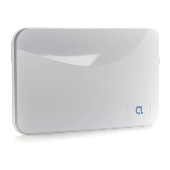
BAT-Connect
is a device that connects to security
panels and provides interactive services, home
automation, and the ability to update the user
interface.
Features
• Three network connectivity paths: cellular, ethernet,
and Wi-Fi
• Provides interactive services, home automation,
and the ability to update the user interface on
existing panels without panel replacement
• Full interactive support of Honeywell Vista and DSC
Power Series panels
• Telco event capture and reporting on most legacy
panels using phone line emulation
Installation Overview
1. Set up an account in the AlulaConnect portal.
2. Program the panel to use the BAT-Connect. (Refer
to the programming section for your panel.)
3. Mount the BAT-Connect to a wall using the
mounting holes on the back plate.
• Maximum cable length to the panel:
18 gauge wire = 350 feet
22 gauge wire = 130 feet
24 gauge wire = 75 feet
4. Wire the panel to the BAT-Connect. (Refer to the
wiring diagram section for your panel.)
5. Set up the network communication path.
Connecting via ethernet:
Plug in cable and ensure ethernet LED is on.
Connecting via cellular:
Verify cellular LED is on and verify signal
strength. (See page 8 for signal strength.)
Verify proper enrollment and operation using your control panel's installation manual.
BAT-Connect Communicator
Cover Securing Screw
Mounting Screws
Wall Tamper Screw
(Do not overtighten mounting)
Tie Wrap
Holes
Wiring Breakouts
I
Advertisement
Table of Contents

Subscribe to Our Youtube Channel
Summary of Contents for Alula BAT-Connect
- Page 1 22 gauge wire = 130 feet 24 gauge wire = 75 feet Wall Tamper Screw (Do not overtighten mounting) 4. Wire the panel to the BAT-Connect. (Refer to the wiring diagram section for your panel.) 5. Set up the network communication path. Connecting via ethernet: Plug in cable and ensure ethernet LED is on.
- Page 2 5. If WPS is unavailable, Wi-Fi credentials can alternately be entered in the AlulaConnect portal. 6. Reconnect ethernet cable (if used). 6. Installation is complete. After installing BAT-Connect, or modifying any panel programming, verify proper operation and reporting of all event codes using your control panel’s installation manual.
- Page 3 5. Exit programming mode and power down the Vista system. 6. Connect the Vista system and BAT-Connect as shown in the wiring diagram on the next page. 7. For Vista 21IP panels, Internal IP/GSM jumper needs to be set to “OFF”.
- Page 4 DATA OUT YELLOW • Vista control panels require connection to panel bus only. Tip/ring connections are not required. • See below for supported Vista panels. If Vista panel is not listed, please contact Alula Support. Compatible Panels • Vista 15P •...
- Page 5 “02”(optional) 5. Exit programming mode and power down the DSC system. 6. Connect the DSC system and the BAT-Connect as shown in the wiring diagram on the next page. 7. Power up the DSC system. • The DSC control panel will begin automatic configuration. Panel keypads will be unavailable during this time.
- Page 6 • DSC control panels require connection to panel bus and Tip & Ring. • Tip & Ring should not be wired to BAT-Connect using the same multi-conductor cable as the panel bus wiring. Tip & Ring should be in a separate cable.
- Page 7 • Any control panel can be supported for event reporting as long as it provides Tip & Ring connection and transmits Contact ID. • Tip & Ring should not be wired to BAT-Connect using the same multi-conductor cable as the panel wiring. Tip & Ring should be in a separate cable.
-
Page 8: Operation
See panel programming sections above. Remote control of the system can be done through the Alula apps on Honeywell Vista and DSC panels. Arming and disarming control and status apply only to partition 1. Enroll/Reset button will reset the BAT-Connect if held for 5 seconds, and if held for approximately 10 seconds will factory default the BAT-Connect. -
Page 9: Troubleshooting
• Mount as high in the building as possible to optimize cellular strength. • An auxiliary power supply may be used to power BAT-Connect. This power supply must have a backup battery to provide power if AC power fails. Ensure voltage is 12 VDC. -
Page 10: Antenna Options
Antenna Options Internal antenna - RE048 • Good Performance • Offers a compact solution Wall Drop antenna - RE036 • 8-foot antenna • Better performance • Antenna can be hidden in the wall Wall Drop antenna - RE036-0 • 1-foot antenna •... - Page 11 High Gain antenna - RE046 • Best performance • Offers optimal cellular performance Antenna Removal and Installation 1. Pull up gently on the internal antenna’s connector to release it from the cellular module. 2. Remove the internal antenna. 3. Break out the plastic plug in hole at top of enclosure. 4.
-
Page 12: Specifications
TRADEMARKS This device complies with Part 15 of the FCC rules. Operation is Alula is a trademark owned by Alula Holdings, LLC. Alula products subject to the following two conditions: will function with one of either Honeywell or DSC systems. However, no Alula product is produced by, endorsed by, nor is officially (1) This device may not cause harmful interference.


Need help?
Do you have a question about the BAT-Connect and is the answer not in the manual?
Questions and answers