Table of Contents
Advertisement
Quick Links
Advertisement
Table of Contents

Related Manuals for Ubiquiti SolarBeam SB-700-1

Summary of Contents for Ubiquiti SolarBeam SB-700-1
- Page 1 Off-Grid 716Wh Battery Models: SB-700-1, SB-700-2, SB-700-3...
-
Page 3: Package Contents
Quick Start Guide Off-Grid 716Wh Battery Models: SB-700-1, SB-700-2, SB-700-3 TERMS OF USE: Ubiquiti radio devices must be professionally installed. Shielded Ethernet cable and earth grounding must be used as conditions of product warranty. TOUGHCable is designed for ™ outdoor installations. It is the customer’s responsibility to follow local country regulations, including operation within legal frequency channels, output power, and Dynamic Frequency Selection (DFS) requirements. - Page 4 SolarBeam Quick Start Guide Hardware Overview Electronics Compartment The compartment is located on the back of the main solar panel. 24VDC Out Fuse Data SLA|Tbatt SW/Gel Reset Components Description Connects to PV cabling. Optional: You can connect a lead-acid battery. SLA|Tbatt The maximum charge voltage is 28.2V (default: AGM/flooded) or 27.2V (gel).
-
Page 5: Installation Requirements
Ethernet connections and should be grounded through the AC ground of the PoE. We recommend that you protect your networks from harmful outdoor environments and destructive ESD events with industrial-grade, shielded Ethernet cable from Ubiquiti Networks. For more details, visit www.ubnt.com/toughcable... - Page 6 SolarBeam Quick Start Guide Installation Guidelines Orient the panel towards the south (or towards the north if in the southern hemisphere. If you prefer to set the angle just once, we recommend to use the adjustment angle for your latitude in winter. Angle of Adjustment Latitude (Winter) Latitude (Summer)
-
Page 7: Installation Overview
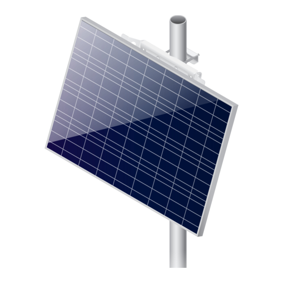
Installation Overview Installation Overview Installation includes the following: • Hardware Installation Mount the solar panel(s). • Connecting the SolarBeam Connect the cables. Accessing the Configuration Interface • Configure settings. Hardware Installation If you have SB-700-2 or SB-700-3, install the main solar panel first before installing the other panels. - Page 8 SolarBeam Quick Start Guide 2. Mount the Mounting Bracket on the pole and secure it. a. Place the Mounting Bracket against the pole. b. Slide the slot of each Pole Clamp over the adjacent Carriage Bolt. c. Tighten the Flange Nuts of the bolts to 25 N ∙ m to secure the Mounting Bracket to the pole.
- Page 9 Hardware Installation 3. Attach the Strut to the Mounting Bracket using two Bracket Screws. Hand-tighten only. 4. Insert the Panel into the Mounting Bracket and Strut.
- Page 10 SolarBeam Quick Start Guide 5. Attach the Panel to the Mounting Bracket and Strut using four Bracket Screws. Hand-tighten only. 6. Adjust the angle of the Panel based on your latitude (refer to the Installation Guidelines section on page 4). Then tighten the six Bracket Screws to 1.7 N ∙ m.
- Page 11 Hardware Installation Instructions for SB-700-2 or SB-700-3 Follow the pole mounting instructions for your additional panels. For the SB-700-3, ensure that your main solar panel is installed in the middle position. SB-700-2 SB-700-3...
-
Page 12: Wall Mounting
SolarBeam Quick Start Guide Wall Mounting 1. Position and securely fasten the flat side of the Mounting Bracket to the wall using six M8 or 5/16" screws (not included). 2. Attach the Strut to the Mounting Bracket using two Bracket Screws. - Page 13 Hardware Installation 3. Insert the Panel into the Mounting Bracket and Strut. Then attach the Panel to the Mounting Bracket and Strut using four Bracket Screws. Hand-tighten only. 4. Adjust the angle of the Panel based on your latitude (refer to the Installation Guidelines section on page 4).
- Page 14 SolarBeam Quick Start Guide Instructions for SB-700-2 or SB-700-3 Follow the wall mounting instructions for your additional panels. For the SB-700-3, ensure that your main solar panel is installed in the middle position. SB-700-2 SB-700-3...
- Page 15 Connecting the SolarBeam Connecting the SolarBeam Before you begin, unscrew the thumbscrews to remove the port cover. When you have finished your connections, hand-tighten the grommets and replace the port cover. Connecting to a Battery (Optional) You can use flexible conduit or an optional cable gland (not included) for your connection to an external battery.
- Page 16 SolarBeam Quick Start Guide 2. Feed a DC cable (not included, maximum size: 14AWG) through the hole and wire to the SLA terminal block. WARNING: We strongly recommend that you add an appropriate DC breaker (interrupter) between the SLA|Tbatt terminal block and external battery to increase safety during installation or maintenance.
-
Page 17: Connecting Ethernet
Connecting the SolarBeam Connecting to the DC Output (Optional) Note: Ensure that your network device supports the supplied voltage. 1. Remove the Fuse to disable the DC output. 2. Feed the included DC Cable through the grommet and wire it to the 24V DC Output terminal block. - Page 18 SolarBeam Quick Start Guide Connecting PV Cabling Instructions for SB-700-1 Connect the Attached PV Cables to its electronics compartment. Attached PV Cables 1. Feed the Attached PV Cables through the grommet. 2. Wire the positive (+) PV Cable to the positive (+) input of the PV terminal block.
- Page 19 Connecting the SolarBeam Instructions for SB-700-2 or SB-700-3 You will use the included Splice Kit to connect the solar panels. Splice Kit Components Polyolefin Tubing Splice Blocks Grommets Plugs 1. Cut the included PV Cable to the two lengths needed for making positive (+) and negative (-) polarity connections from the Splice Blocks to the electronics compartment.
- Page 20 SolarBeam Quick Start Guide 3. Refer to the polarity diagram for your specific model. Then proceed to the Splicing the PV Cabling section. SB-700-2 (Positive or Negative Polarity) From Electronics Compartment Main Panel Second Panel SB-700-3 (Positive or Negative Polarity) From Electronics Compartment Main Panel Second Panel Third Panel...
- Page 21 Connecting the SolarBeam 3. Feed the included PV Cable from the electronics compartment of the main solar panel through the Polyolefin Tubing. 4. Feed the Attached PV Cables from all of the solar panels through the Grommet and insert them into the Splice Block. 5.
-
Page 22: Accessing The Configuration Interface
Press enter (PC) or return (Mac). 4. The login screen will appear. Enter ubnt in the Username and Password fields. Read the Ubiquiti License Agreement, and select I agree to the terms of this License Agreement to accept it. - Page 23 Accessing the Configuration Interface 5. The SolarBeam Dashboard screen will appear. Click Services. 6. To enable 24VDC output, select Output Voltage (24V DC). WARNING: Before enabling 24VDC output, ensure that the connected device supports the supplied voltage. 7. To output 24V passive PoE on the Data port, select Output Voltage (24V DC) and then click POE ON.
-
Page 24: Specifications
SolarBeam Quick Start Guide Specifications SB-700-1, SB-700-2, SB-700-3 Dimensions (per Panel) 1005 x 670 x 200 mm (39.57 x 26.38 x 7.87") Weight Mount 5.1 kg (11.24 lb) SB-700-1 (w/o Mount) 19.1 kg (42.11 lb) SB-700-2 (w/o Mount) 30.5 kg (67.24 lb) SB-700-3 (w/o Mount) 41.9 kg (92.37 lb) Enclosure... -
Page 25: Safety Notices
Safety Notices Safety Notices 1. Read, follow, and keep these instructions. 2. Heed all warnings. 3. Only use attachments/accessories specified by the manufacturer. WARNING: Do not use this product in location that can be submerged by water. WARNING: Avoid using this product during an electrical storm. -
Page 26: Limited Warranty
(VI) has no original Ubiquiti MAC label, or is missing any other original Ubiquiti label(s); or (VII) has not been received by Ubiquiti within 30 days of issuance of the RMA. In addition, the above warranty shall apply only if: the product has been properly installed and used at all times in accordance, and in all material respects, with the applicable Product documentation;... - Page 27 No Products will be accepted for replacement or repair without obtaining a Return Materials Authorization (RMA) number from UBIQUITI NETWORKS during the warranty period, and the Products being received at UBIQUITI NETWORKS’ facility freight prepaid in accordance with the RMA process of UBIQUITI NETWORKS.
-
Page 28: Limitation Of Liability
Limitation of Liability EXCEPT TO THE EXTENT PROHIBITED BY LOCAL LAW, IN NO EVENT WILL UBIQUITI OR ITS SUBSIDIARIES, AFFILIATES OR SUPPLIERS BE LIABLE FOR DIRECT, SPECIAL, INCIDENTAL, CONSEQUENTIAL OR OTHER DAMAGES (INCLUDING LOST PROFIT, LOST DATA, OR DOWNTIME COSTS), ARISING... -
Page 29: Industry Canada
Compliance This radio transmitter (FCC ID: SWX-SB700) has been approved by FCC to operate with the antenna types listed below with the maximum permissible gain and required antenna impedance for each antenna type indicated. Antenna types not included in this list, having a gain greater than the maximum gain indicated for that type, are strictly prohibited for use with this device. -
Page 30: Rf Exposure Warning
SolarBeam Quick Start Guide Cet émetteur radio (IC: 6545A-SB700) a été approuvée par Industrie Canada pour l’exploitation avec l’antenne types énumérés ci-dessous avec le gain maximal admissible et requis l’impédance de l’antenne pour chaque type d’antenne indiqué. Types d’antenne non inclus dans cette liste, ayant un gain supérieur au gain maximal indiqué... - Page 31 Compliance RoHS/WEEE Compliance Statement English European Directive 2012/19/EU requires that the equipment bearing this symbol on the product and/or its packaging must not be disposed of with unsorted municipal waste. The symbol indicates that this product should be disposed of separately from regular household waste streams.
- Page 32 SolarBeam Quick Start Guide Español La Directiva 2012/19/UE exige que los equipos que lleven este símbolo en el propio aparato y/o en su embalaje no deben eliminarse junto con otros residuos urbanos no seleccionados. El símbolo indica que el producto en cuestión debe separarse de los residuos domésticos convencionales con vistas a su eliminación.
-
Page 33: Declaration Of Conformity
Ezennel UBIQUITI NETWORKS kijelenti, hogy ez a UBIQUITI NETWORKS készülék megfelel az alapvető követelményeknek és más [Hungarian] vonatkozó 2014/30/EU, 2014/35/EU irányelvek rendelkezéseit. Íslenska Hér, UBIQUITI NETWORKS, því yfir að þetta UBIQUITI NETWORKS tæki er í samræmi við grunnkröfur og önnur viðeigandi ákvæði tilskipana [Icelandic] 2014/30/ESB, 2014/35/ESB. Italiano Con la presente, UBIQUITI NETWORKS, dichiara che questo dispositivo UBIQUITI NETWORKS, è... - Page 34 ďalšími [Slovak] relevantnými ustanoveniami smernice 2014/30/EÚ, 2014/35/EÚ. Español Por medio de la presente UBIQUITI NETWORKS declara que este dispositivo UBIQUITI NETWORKS, cumple con los requisitos [Spanish] esenciales y cualesquiera otras disposiciones aplicables o exigibles de las Directivas 2014/30/UE, 2014/35/UE.
- Page 36 ©2017 Ubiquiti Networks, Inc. All rights reserved. Ubiquiti, Ubiquiti Networks, the Ubiquiti U logo, the Ubiquiti beam logo, SolarBeam, and TOUGHCable are trademarks or registered trademarks of Ubiquiti Networks, Inc. in the United States and in other countries. All other trademarks are the property of their respective owners.