Table of Contents
Advertisement
Quick Links
Download this manual
See also:
Manual
Advertisement
Table of Contents

Related Manuals for Adam Equipment AE 403 Series


Summary of Contents for Adam Equipment AE 403 Series
- Page 1 Adam Equipment AE 403 Series Indicator Service Manual Software revisions V1.00 and above © Adam Equipment Company 2019...
- Page 2 Easy Reference: Model name of the scale: Serial number of the unit: Software revision number (Displayed when power is first turned on): Date of Purchase: Name of the supplier and place: © Adam Equipment Company 2019...
-
Page 3: Table Of Contents
9.0 U-BRACKET ASSEMBLY .................... 22 10.0 CHANGING LOAD CELL AND RS232 CABLE ............22 11.0 CHANGING BATTERY or BATTERY CABLE ............25 12.0 CHANGING TRANSFORMER ................... 26 13.0 CHANGING OVERLAY ....................28 14.0 ACCESSORIES & SPARE PARTS ................28 © Adam Equipment Company 2019... -
Page 4: Introduction
The indicator has high voltage inside. This high voltage can be lethal. When using the indicator, indicator power plug must connect to a reliable earthed external power. When service the indicator, power must be disconnected, it is essential to separate display plug from external power. © Adam Equipment Company 2019... -
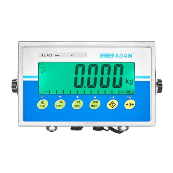
Page 5: Panel Interfaces
See section 11 for more installation details. RELAY INTERFACES The indicator has relay interfaces option. If you need this option, please contact Adam Equipment or your dealer. See the User manual section 10.0 for more details. © Adam Equipment Company 2019... -
Page 6: Indicator Menus
1-9. Use [] directional key to move to the next digit [] Entering the correct password [1946] will bring you to the supervisor menu. The displays • will show the first parameters, called “AdCnT”. © Adam Equipment Company 2019... -
Page 7: Adcnt
The range of the ADC counts will depend upon the load cell used and if the bracket is in place or not. 5.1.2 “dvAL” This parameter is dual range. © Adam Equipment Company 2019... -
Page 8: Appro
] key to enter this parameter, display will show “2.0”. Use Press the [ [] [] key to change parameter, there are 0.5,1.0,1.5,2.0,2.5,3.0 parameters available to select, press [ ] to accept the selected parameter. 5.1.6 “p-zEro” This parameter sets the power on zero range © Adam Equipment Company 2019... -
Page 9: K-Zero
[CE] key can clear original readings. Use [] [] key to change the parameter, use [] key to move to the next digit, enter the actual acceleration of gravity for operation location and press [ ] to accept. © Adam Equipment Company 2019... -
Page 10: Linear
] to accept the selected parameter the reading goes to zero “disp” shows the tare value, and only allows, manual clearing of the tare. 5.1.13 “doT” Sets whether the decimal point is displayed as a dot or a comma. © Adam Equipment Company 2019... -
Page 11: C-Con
This section describes the parameters available to the dealers for setting up the indicator. Access to these parameters is controlled by password. © Adam Equipment Company 2019... -
Page 12: L-Cal
[] key [] [] to move to the next digit. Generally load 1 is set to1/2 of the capacity. Select integer for actual weight and press [ ] to accept. © Adam Equipment Company 2019... -
Page 13: Adc
[ ] to accept. USER MENUS The user has access to a menu to allow calibration of weight without the normal limitations put on the calibration during the user methods of setting them © Adam Equipment Company 2019... -
Page 14: Indicator Parameters
] to [] and [] enter a parameter. • Press [Esc] to exit the scale parameter section and return to normal weighing. This group of parameters is used to control the operation of the scale. © Adam Equipment Company 2019... - Page 15 Rs 2 Brings up RS232 menu 2 PC, Cmd S-id Set Scale ID To be entered manually 000000 U-id Set User ID To be entered manually 000000 rechar Indicates time to recharge © Adam Equipment Company 2019...
- Page 16 Set 1# RS232 interface, PC, Cmd, Print including PC, command, print setting Rs 2 Set 2# RS232 interface PC, Cmd S-id Set number for the scale Manual input U-id Set operator number Manual input rechar Display charging current © Adam Equipment Company 2019...
-
Page 17: Rs-232 Parameters Rs232
[Printer/device] Select the printer or LP50 device to print to [Number of Copy 1 Copy 1 Select the number of copies] Copy 2 copies Copy 3 Copy 4 Copy 5 Copy 6 Copy 7 Copy 8 © Adam Equipment Company 2019... -
Page 18: Pc Settings
RS-232 INTERFACE The AE 403 indicator is supplied with bi-directional RS-232 interface as standard. The scale when connected to a printer or computer outputs the weight with the selected weighing unit through the RS-232 interface. © Adam Equipment Company 2019... -
Page 19: Connection Of Load Cell
6: Pin +IN +Signal 7: Pin –IN -Signal 3: Pin AGND Shield 1: Pin +E, +Excitation 2: Pin +S +Sense 4: Pin –E -Excitation 5: Pin -S -Sense © Adam Equipment Company 2019... -
Page 20: Load Cell Wire Solder With Pcb
Before connecting the wire, please make sure external power has been cut off. 8.2.1 Screw out 12 screws at the back of the indicator with correct tool and keep the screws properly. screwx12 Rubber © Adam Equipment Company 2019... - Page 21 8.2.4 Remove the screw fixing the PCB, generally 4pcs, for some models might be 5pcs. Lift up the PCB board carefully. © Adam Equipment Company 2019...
- Page 22 AD count. Press the weighing frame or weighing platform with your hand. When you can see the value is increasing, it indicates load cell connection is correct. Otherwise, you need to connect it again. © Adam Equipment Company 2019...
- Page 23 Do NOT tighten screws working from one screw to the screw next and so on. After tightening it, the clearance between front cover and rear surroundings should be consistent. Screw x12 Rear cover Rubber sealing ring Front cover © Adam Equipment Company 2019...
-
Page 24: U-Bracket Assembly
10.1 According to section 8.2.1, 8.2.2, 8.2.4, take off the PCB, then remove the protection glue for the cable, solder the cable to the PCB board with electric soldering iron and clean the PCB. © Adam Equipment Company 2019... - Page 25 10.3 Remove the metal cover, go through the new cable to metal cover rubber ring, then connect to corresponding holes on the indicator. Nut can be fit and tightened inside the indicator. Solder the cable on the PCB as required below. © Adam Equipment Company 2019...
- Page 26 10.4 Put glass cement on the soldering position on the PCB. 10.5 Follow the steps described in section 11.2.9, fit the rear cover and screw tight the load cell or the metal cover outside RS232 connector, then replace load cell or RS232 cable. © Adam Equipment Company 2019...
-
Page 27: Changing Battery Or Battery Cable
Put a 3mm double faced adhesive tape on the battery first, then put and fix the battery to the rear cover and connect battery wire to the PCB. 11.3 Follow section 8.2.9, fit the rear cover, now battery and battery wire replacement completes. © Adam Equipment Company 2019... -
Page 28: Changing Transformer
12.3 Screw out the last nut from power interference, take out the transformer. Go through the longer end of the new transformer wire from the indicator internally to the interface hole externally. Transformer wire goes through rear rubber cap, see the picture for nut order © Adam Equipment Company 2019... - Page 29 12.6 As described in section 8.2.9, fit the rear cover. Then connect the power plug and transformer wire, now transformer replacement completes. You can see the picture for a finished Euro power connector. © Adam Equipment Company 2019...
-
Page 30: Changing Overlay
Euro Plug (10-16A 230VAC) 30340 13767 Main adaptor 3.03.4.0.13768 Power plug, American 3.03.4.0.13772 Power plug, Euro 3104010635 7 pin connectors,female 3104010633 4 pin connectors,female 31020 14653 AE 403 in use cover Adam DU Data Collection Program © Adam Equipment Company 2019... - Page 31 WARNING: This product includes a sealed lead-acid battery which contains chemicals known to the State of California to cause cancer and birth defects or other reproductive harm. Adam Equipment products have been tested with, and are always supplied with mains power adaptors which meet all legal requirements for the intended country or region of operation, including electrical safety, interference and energy efficiency.
- Page 32 © Copyright by Adam Equipment Co. All rights reserved. No part of this publication may be reprinted or translated in any form or by any means without the prior permission of Adam Equipment. Adam Equipment reserves the right to make changes to the technology, features, specifications and design of the equipment without notice.
Need help?
Do you have a question about the AE 403 Series and is the answer not in the manual?
Questions and answers
why under appears on the scale