
Related Manuals for Adam Equipment GK-Mplus


Summary of Contents for Adam Equipment GK-Mplus
- Page 1 Adam Equipment GK-Mplus INDICATOR Software revision: GK‐Mplus V1.02 ©Adam Equipment Company 2019...
- Page 2 Easy Reference: Model name of the indicator: Serial number of the unit: Software revision number (Displayed when power is first turned on): Date of Purchase: Name of the supplier and place: ...
-
Page 3: Table Of Contents
CONTENTS PN 3.05.6.6.15666, Rev A, November 2019 INTRODUCTION ....................... 3 SPECIFICATIONS ..................... 4 INSTALLATION ......................5 UNPACKING ......................5 LOCATING ......................5 CONNECTION ......................6 KEYPAD AND DISPLAY ................... 7 DISPLAY ........................ 7 DISPLAY ........................ 9 5.2.1 SYMBOLS AND INDICATORS ................9 CALIBRATION COUNTER FOR APPROVED INDICATORS ......... - Page 4 15.2.6 F6 -SUCCESSIVE TARE ................41 15.2.7 F7 –ADC COUNTS ..................41 15.2.8 F8 –ZERO MODE ..................42 15.2.9 F9 –FILTER SETTINGS ................42 15.2.10 F10 –CALIBRATION COUNT ..............42 15.2.11 F11 –SELECT APPROVALS STANDARD ..........43 15.2.12 F12 –DEFAULT PARAMETERS TO FACTORY VALUES ...... 43 16.0 REPLACEMENT PARTS AND ACCESSORIES ..........
-
Page 5: Introduction
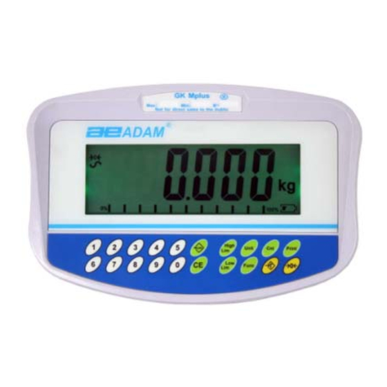
The GK-Mplus is supplied with a RS-232 bi-directional interface and real time clock (RTC). The GK-Mplus has a sealed keypad with colour coded buttons and a large easy to read liquid crystal type display (LCD) supplied with a multicolour illumination. -
Page 6: Specifications
SPECIFICATIONS INPUT SECTION Load Cells Single loadcell maximum 500 ohms Connection 6 wires 2 excitation, 2 sense, 2 signal Excitation 5Vdc Sensitivity 1.00uv/e Linearity 0.01% FS Zero Range 0-10mv Signal range 0-39mv ADC Sensitivity Approximately 0.002 µv/ADC count DIGITAL SECTION Maximum Range Typically 1kg –... -
Page 7: Installation
INSTALLATION UNPACKING This indicator must be connected to a load cell platform and calibrated as necessary to match the platform and user requirements. See Section 15 for set-up information. The user’s application and the technical specifications of the platform or load cell will determine the necessary configuration. -
Page 8: Connection
The cable length should be as short as possible, using a large size wire to minimise errors due to resistance in the leads. GK-Mplus model must use the 6 wire connection and has certain limitations for wire size and length. Refer to the Approval Test Certificate for details. © Adam Equipment Company 2019 ... -
Page 9: Keypad And Display
Figure 1A shows the connections to a 6 wire load cell. Figure 1B shows a preferred method to attach a 4 wire load cell, using a 6 conductor cable to go from the indicator to the platform or load cell where it connects to the 4 wires from the load cells. Excitation and sense wires are connected together near the load cell. - Page 10 [Low Limit] It sets the limits for check weighing None and allows setting of either the low & limit or the high limit or both. [High Limit] [Lim] It stores and recalls any of 10 preset None limits [Func] This is used to select percent None...
-
Page 11: Display
DISPLAY 5.2.1 SYMBOLS AND INDICATORS The LCD has unique symbols to indicate the following: 0 The display is at Zero The scale is Stable Net weight- The scale has been tared kg / g Symbols shown for the units Capacity Tracker- A bar graph indicating the proportion of the scale capacity being used by the weight on the pan Battery Status... -
Page 12: Calibration Counter For Approved Indicators
CALIBRATION COUNTER FOR APPROVED INDICATORS With approved GK-Mplus indicators we have the ability to control access to the calibration or metrology parameters using a passcode to limit access. The requirements for doing this stipulate the code should be apparent and recorded in a suitable location on the indicator. -
Page 13: Battery
BATTERY The indicators can be operated from the rechargeable battery, if desired. The battery life is determined by the number and impendence of the load cells connected. With a single load cell and backlight disabled the life is approximately 70 hours before needing to be recharged. -
Page 14: Operation
10.0 OPERATION 10.1 ZEROING You can press the [Zero] key at any time to set the zero point, from which, all other weighing and counting is measured. This will usually be necessary when the platform is empty. When the zero point is obtained the display will show the zero indicator. ... -
Page 15: Weighing
NOTE: When the container is removed a negative value will be shown. If the indicator was tared just before removing the container, this value is the gross weight of the container plus all products which were removed. The zero indicator will also be on as the platform is back to the same condition it was when [Zero] was pressed last. - Page 16 Either place 10 parts on the platform for determining the average piece weight or use a different number of parts. For example, place 20 parts on the platform, press [CE] to clear the last values and then enter the value 20 using the numeric keypad. ...
-
Page 17: Check-Weighing
To count a different sample quantity, press the [Cnt] key. The display will show the last used sample size. Either use this sample size with a different part or enter a new sample size as above . ... -
Page 18: Setting Up While Weighing
Mass on the platform is above the high limit Green Mass is between the limits Amber Mass is below the low limit The limits can be locked by the manager. A Limit Password must be used to change the limits or recall other limits from memory. If Limit Password is enabled then enter the password which will allow you to change the limits or the operation of the beeper. -
Page 19: Limits Storing And Recalling
NOTE: 1. The weight must be greater than 20 scale divisions for the check-weighing to operate. 2. To disable the check weighing function, enter zero into both the limits as described above. When the current limits are shown, press [CE] to clear the settings, then press [Tare] to store the zero values. -
Page 20: Percent Weighing
If you wish to recall any of the pre-stored limits, press [Tare] when “rECALL” is displayed. The display shows “rEC ”. Enter the number corresponding to the desired memory location (0 ” to 9) to be recalled. “rEC X will be displayed for 2 seconds indicating the values stored in the location “X”... - Page 21 Press [Tare] again to enter percent weighing. The indicator will set the sample mass on the platform as 100% reference weight. NOTE: If there is no reference weight on the pan and percent weighing function is entered, pressing [Tare] again will return the indicator to normal weighing.
-
Page 22: Animal (Dynamic) Weighing
10.8 ANIMAL (DYNAMIC) WEIGHING The indicator can be set to animal (dynamic) weighing for weighing any items that are unstable or may move. See Section 13.4. The indicator uses a special filter to minimise the effects of any movement on the platform. ... -
Page 23: Animal Weighing Procedure
10.8.1 Animal Weighing Procedure With the platform empty the display will show zero weight. Place containers or blankets onto the platform and press the [Tare] key to zero the display. The indicator may go into the animal weighing procedure when the items are placed on the platform but will return to showing zero when the [Tare] key is pressed. -
Page 24: Manual Accumulation
10.9.1 Manual Accumulation When the indicator is set to manual accumulation, the weight displayed will be stored in the memory when the [Print] key is pressed and the weight is stable. Remove the weight and press [Print] when the indicator is at zero. The display will show ... -
Page 25: Automatic Accumulation
To print the total, press [Print] to recall and then immediately press [Print] the second time to print the results. To erase the memory, press [Print] to view the total and then immediately press [CE] to clear the memory. ... -
Page 26: Rs-232 Specification
11.0 RS-232 SPECIFICATION The GK indicator is supplied with bi-directional RS-232 interface as standard. The indicator when connected to a printer or computer outputs the weight with the selected weighing unit through the RS-232 interface. Default Specifications : RS-232 output of weighing data ASCII code 4800 Baud (user selectable) - Page 27 Data Format-Normal Output: Only weight value along with the weighing unit is printed. If Percent weighing is used then % is shown in place of weighing units. <cr><lf> <cr><lf> 12/09/2006 <cr><lf> Time 14:56:27 <cr><lf> <cr><lf> Scale ID 123456 <cr><lf> If ID is zero, it is left blank User ID 234567 <cr><lf>...
- Page 28 Data Format- Memory Recall Output: <cr><lf> Date 12/09/2006 <cr><lf> Time 14:56:27 <cr><lf> <cr><lf> Scale ID 123456 <cr><lf> User ID 234567 <cr><lf> <cr><lf> ------------------<cr><lf> TOTAL <cr><lf> 1.234 kg <cr><lf> 10 pcs <cr><lf> <cr><lf> ------------------<cr><lf> <cr><lf> Data Format- Continuous Output- Normal weighing: Net Weight (or Gross wt.) ...
- Page 29 NOTE: 1. The accumulated total will not be sent to the RS-232 when the continuous print is turned on. 2. The continuous print will only be for the current weight and the display data. 3. In other languages the format is the same but the text will be in the language selected.
-
Page 30: Input Commands Format
11.1 INPUT COMMANDS FORMAT The indicator can be controlled with the following commands. Press the [Enter] key of the PC after each command. T<cr><lf> Tares the indicator to display the net weight. This is the same as pressing [Tare]. Z<cr><lf>... -
Page 31: Calibration
12.0 CALIBRATION The GK-Mplus indicator and approved bench scales models are sealed to prevent unauthorised calibration. Contact Adam Equipment or your supplier for more details. WARNING: CALIBRATION OF THE SCALES MAY MAKE IT ILLEGAL TO USE THE SCALES FOR SALES OF GOODS. -
Page 32: Parameter Settings
13.0 PARAMETER SETTINGS Pressing the [Func] key allows the user to access the parameters for customising the indicator. The parameters are split into 4 groups: 1. Check weighing parameters, 2. RS-232 parameters 3. Indicator parameters 4. Percent and Animal Weighing Functions ... - Page 33 This group of parameters- enables or disables the percent weighing sets the lock for re-setting the check weighing limits enables or disables the check weighing alarm sets the User Password for check weighing enables or disables the negative check weighing Parameter Description Options...
-
Page 34: Rs-232 Parameters
NOTE: The Check weighing password is separate from the indicator password. If the password is other than 0000, user must enter the password to gain access to “F1 LLk”, “F2 bEP”, “F3 CPS” “F4 nCK”. 13.2 RS-232 PARAMETERS Shortcut to enter this group is to press and hold the [Print] key for 4 seconds. - Page 35 C3 PrM Printing Mode, Manual MA StA, MA StA or Automatic, when Au StA, Stable or Automatic Au Con Continuous C4 Aon AC on AC on Enable or disable the Accumulation AC oFF C5 Ln EnGLi EnGLi Select Language (English) ...
-
Page 36: Indicator Parameters
13.3 INDICATOR PARAMETERS Shortcut to enter this group is to press and hold the [Cnt] Key for 4 seconds. The display will go directly to “S1 Un”. Press [Func] to view the list of parameters. Press [Tare] to enter a parameter. Press [Func] to view the options for the parameter settings. -
Page 37: Percent Weighing And Animal Weighing
FAStESt (1-6) S7 SPS PI _ _ _ _ 0000 Scale Password- If it is anything other than 0000 then the user must enter the password to gain access to indicator parameter settings. Must be entered twice when asked. When complete, will... -
Page 38: Error Messages
14.0 ERROR MESSAGES During the initial power-on testing or during operation, the indicator may show an error message. The meaning of the error messages is described below. If an error message is shown, repeat the step that caused the message. If the error message is still shown then contact your dealer for support. -
Page 39: Service Parameters
Err 20 PLU storage/ reading is more than PLU number above max range of 50 Err ADC Can’t find ADC chip Damaged or missing ADC chip Load cell is damaged. Electronics is damaged. ---OL--- Weight over range Weight over scale range undEr Weight is lower than -25e Weight below scale range... -
Page 40: Using "2006" To Enter The Service Parameters
15.2 USING “2006” TO ENTER THE SERVICE PARAMETERS For the Approved version a jumper can be installed to allow access or the Calibration and Parameter Counters must be enabled (see 15.2.10). Apply power to the indicator. If the jumper has been used the display will ask for a code number, “P ”... -
Page 41: F1 -Calibration
The parameters available are: “F1 CAL” To enter the Calibration “F2 dEC” Decimal Point Position “F3 CAP” Set Capacity and Resolution “F4 Int” Initial Zero Range “F5 rEZ” Re-Zero range “F6 SCS” Successive Tare Enable “F7 Cnt” Display the A/D counts “F8 Zem”... -
Page 42: F2-Decimal Point Position
The display will automatically restart if the calibration is OK. Remove the weight. For the approved indicator the display will then show “JP” “On” indicating the jumper is still in place if the jumper within the indicator was used to access the parameters. Switch off the indicator, and switch it on again to continue with the other Service parameters. -
Page 43: F4 -Initial Zero Range
15.2.4 F4 –INITIAL ZERO RANGE To enter this parameter, press the [Tare] key when “F4 int” is shown. The display will show the current initial zero range. Press the [Func] key to change the value and press [Tare] to accept the value. Press [Zero] to return to weighing. -
Page 44: F8 -Zero Mode
15.2.8 F8 –ZERO MODE To enter this parameter, press the [Tare] key when “F8 ZEm” is shown. Select the Zero mode desired. In all but special cases Zero Mode 1 is used. The other 2 zero modes are for unique locations in the world and effect the +/- range of the zero. Press the [Func] key to change the value. -
Page 45: F11 -Select Approvals Standard
Press the [Func] key to change the value. Press [Tare] to accept the displayed value. Press [Zero] to return to weighing. 15.2.11 F11 –Select Approvals Standard This parameter allows for an approval standard to be set, according to the standard selected, the software will load the relevant parameters defaults, to guarantee the indicator is compliant with the standard selected. -
Page 46: Replacement Parts And Accessories
16.0 REPLACEMENT PARTS AND ACCESSORIES If you need to order any spare parts and accessories, contact your supplier or Adam Equipment. A partial list of such items is as follows- Main Power cord or adaptor for USA versions. In use cover Replacement Battery Printer, etc. © Adam Equipment Company 2019 ... -
Page 47: Service Information
17.0 SERVICE INFORMATION This manual covers the details of operation. If you have a problem with the indicator that is not directly addressed by this manual then contact your supplier for assistance. In order to provide further assistance, the supplier will need the following information which should be kept ready: A. - Page 48 WARRANTY INFORMATION Adam Equipment offers Limited Warranty (Parts and Labour) for the components failed due to defects in materials or workmanship. Warranty starts from the date of delivery. During the warranty period, should any repairs be necessary, the purchaser must inform its supplier or Adam Equipment Company.
-
Page 49: Appendix
APPENDIX PARAMETER LAYOUT for GK Mplus Press the [Func] key to enter Key functions while in this section [Tare] enter a parameter or accept the changes [Func] move to next parameter or option . Functions mode [Low Lim] move to previous parameter or option [Zero] exit parameter or return to weighing FUNC 1 FUNC 2 FUNC 3 FUNC 4 Check weighing parameters RS‐232 Parameters Scale Parameters Scale Parameters F1 LLk oFF C1 on Prt on S1 Un ... - Page 50 ©Adam Equipment Company 2019...
- Page 51 WEEE 2012/19/EU This device may not be disposed of in domestic waste. This also applies to countries outside the EU, per their specific requirements. Disposal of batteries (if fitted) must conform to local laws and restrictions. Cet appareil ne peut être éliminé avec les déchets ménagers. L’élimination de la batterie doit être effectuée conformément aux lois et restrictions locales. Dieses Gerät nicht mit dem Hausmüll entsorgt. Dispositivo no puede ser desechado junto con los residuos domésticos Dispositivo non può essere smaltito nei rifiuti domestici. FCC / IC CLASS A DIGITAL DEVICE EMC VERIFICATION STATEMENT NOTE: This equipment has been tested and found to comply with the limits for a Class A digital device, pursuant to Part 15 of the FCC rules and Canadian ICES‐003/NMB‐003 regulation. These limits are designed to provide reasonable protection against harmful interference when the equipment is operated in a commercial environment. This equipment generates, uses and can radiate radio frequency energy and, if not installed and used in accordance with the instruction manual, may cause harmful interference to radio communications. Operation of this equipment ...
- Page 52 ADAM EQUIPMENT is an ISO 9001:2015 certified global company with more than 40 years’ experience in the production and sale of electronic weighing equipment. Adam products are predominantly designed for the Laboratory, Educational, Health and Fitness, Retail and Industrial Segments. The product range can be described as follows: ‐Analytical and Precision Laboratory Balances ‐Compact and Portable Balances ‐High Capacity Balances ‐Moisture analysers / balances ‐Mechanical Scales ‐Counting Scales ‐Digital Weighing/Check‐weighing Scales ‐High performance Platform Scales ‐Crane scales ‐Mechanical and Digital Electronic Health and Fitness Scales ‐Retail Scales for Price computing For a complete listing of all Adam products visit our website at www.adamequipment.com Adam Equipment Co. Ltd. Adam Equipment Inc. AE Adam GmbH. Maidstone Road, Kingston 1, Fox Hollow Rd. Instenkamp 4 Milton Keynes Oxford, CT 06478 D‐24242 Felde MK10 0BD UK USA Germany Phone:+44 (0)1908 274545 ...
Need help?
Do you have a question about the GK-Mplus and is the answer not in the manual?
Questions and answers