Table of Contents
Advertisement
Change for life
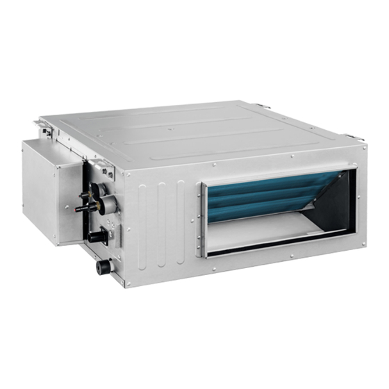
High Static Slim Duct
Installation & Owner's Manual
Original Instructions
DUCT09HP230V1BD
DUCT12HP230V1BD
DUCT18HP230V1BD
DUCT24HP230V1BD
Thank you for choosing Gree residential and commercial air
conditioners. Please read this Owner's Manual carefully before
operation and retain it for future reference.
For more information, please contact your local distributor or visit
www.greecomfort.com for the electronic version. or send an email to
info@twclimate.com.
Advertisement
Table of Contents

Related Manuals for Gree DUCT09HP230V1BD


Summary of Contents for Gree DUCT09HP230V1BD
- Page 1 DUCT09HP230V1BD DUCT12HP230V1BD DUCT18HP230V1BD DUCT24HP230V1BD Thank you for choosing Gree residential and commercial air conditioners. Please read this Owner’s Manual carefully before operation and retain it for future reference. For more information, please contact your local distributor or visit www.greecomfort.com for the electronic version. or send an email to...
- Page 2 Preface For correct installation and operation, please read all instructions carefully. Before reading the instructions, please be aware of the following items: This is the safety alert symbol. It is used to alert you to potential personal injury hazards. Obey all safety messages that follow this symbol to avoid possible injury or death. This mark indicates procedures which, if improperly performed, might lead to the death or serious injury of the user.
-
Page 3: Table Of Contents
Contents 1 Safety Precautions ......................1 2 Product Introduction ......................3 2.1 Names of Key Components ....................3 2.2 Rated Working Condition ....................3 3 Preparations for Installation ....................3 3.1 Standard Fittings ......................... 3 3.2 Location for Installation ....................... 4 3.3 Wiring Requirements...................... -
Page 4: Safety Precautions
Multi Variable Air Conditioners Ducted Type Indoor Unit 1 Safety Precautions (1) Please read this manual carefully and follow the instructions before unit startup and/or service by a licensed HVAC technician. (2) Size power supply wiring by recommendations provided here, or in the product submittals, while adhering to all local codes and regulations. - Page 5 HVAC technician for service. Operating the system under these adverse conditions may result in irreparable damage or personal injury. personal injury property loss caused improper installation, improper debugging, unnecessary or improper repair/servicing or not following the instructions in this manual is not the responsibility of Gree Electric Appliances, Inc. of Zhuhai.
-
Page 6: Product Introduction
Multi Variable Air Conditioners Ducted Type Indoor Unit 2 Product Introduction 2.1 Names of Key Components Fig 2.1.1 Drain Control Liquid Air-return Support Name Filter Bracket Pipe pipe pipe Opening Outlet 2.2 Rated Working Condition Indoor Side Condition Outdoor Side Condition Dry Bulb Temp °C( ℉... -
Page 7: Location For Installation
Multi Variable Air Conditioners Ducted Type Indoor Unit Name Appearance Q'ty Usage M10 Washer (Spring Washer To be used together with the hanger bolt for M10X2.6) installing the unit. Insulation To insulate the gas pipe Insulation To insulate the liquid pipe Sponge To insulate the drain pipe Fastener... -
Page 8: Wiring Requirements
(3) Do not connect power until all installation work is finished. 3.3 Wiring Requirements (1) Power Supply and Breaker Capacity Fuse Model Power Supply Capacity(A) DUCT09HP230V1BD DUCT12HP230V1BD DUCT18HP230V1BD 208/230V-1ph-60Hz DUCT24HP230V1BD (1) Use only copper wire for power supply wiring. Make sure the operating temperature is consistent with the wire values. -
Page 9: Installation Instructions
Equip with a inspection hatch after lifting the unit. For the convenience of maintenance, the service port should be on one side of the electric box and below unit’s lower level. Fig 4.1.1 Below are dimensions of A, B, C, etc. for different models: Unit:mm(in.) Model DUCT09HP230V1BD DUCT12HP230V1BD (29-1/8) (19-11/16) (32-11/16) (11-13/16) - Page 10 Multi Variable Air Conditioners Ducted Type Indoor Unit 4.1.2 Suspend the indoor unit (1) Drill bolt holes and install bolts 1) Stick the reference cardboard on the installation position; drill 4 holes according to the hole site on the cardboard as shown in fig 4.1.3; diameter of drilling hole is according to the diameter of expansion bolt and the depth is 60-70mm(2-3/8~2-3/4 in.), as shown in fig 4.1.4.
-
Page 11: Refrigerant Pipe Connection
Multi Variable Air Conditioners Ducted Type Indoor Unit NOTICE! 1) Before startup, make sure to securely connect all refrigerant lines, drainage hose, control wire for the wired controller, and connection wire for indoor unit. 2) When drilling holes on ceiling (air return outlet or air outlet), you will need to reinforce the ceiling to prevent vibration. -
Page 12: Drainage Pipe Installation And Drainage System Testing
Multi Variable Air Conditioners Ducted Type Indoor Unit 4.3 Drainage Line Installation and Drainage System Testing 4.3.1 Notice for Installation of Drain Line (1) The drain line should be short and the downward slant should be at least 1%~2% in order to drain condensation properly. (2) The diameter of drain line should be greater than or equal to the diameter of drain connection. - Page 13 Multi Variable Air Conditioners Ducted Type Indoor Unit (5) Install the trap as shown in following Fig 4.3.5. (6) Install one trap for each unit. (7) Allow clearance for cleaning trap. Fig 4.3.5 (8) The horizontal pipe can be connected to vertical pipe in the same level; please select the connection way as shown in following fig.
- Page 14 Multi Variable Air Conditioners Ducted Type Indoor Unit Model DUCT09HP230V1BD DUCT12HP230V1BD 150(5-7/8) 850(33-1/2) 800(31-1/2) DUCT18HP230V1BD DUCT24HP230V1BD (10) Drain pipes should have a downward slope of at least 1%~2%, in order to prevent pipes from sagging install hanger brackets at intervals of 1000~1500mm(39-3/8~59 in.).
-
Page 15: Installation Of Air Duct
Multi Variable Air Conditioners Ducted Type Indoor Unit 1) Connect the drain hose to the other drain connection pipe of water tray and inject approximately 1L water. (Remove the drain hose after testing and then put a plug in water tray.) 2) Spray 1L water on evaporator with sprayer. - Page 16 4.4.1 Shape and Size of Supply and Return Air Opening Unit: mm(in.) Fig 4.4.1 Air Supply Outlet Fig 4.4.2 Return Air Opening Size of Supply Air Outlet Size of Return Air Opening Model DUCT09HP230V1BD DUCT12HP230V1BD (7-5/8) (17-3/4) (10-3/8) (26) (1-1/8)
- Page 17 Multi Variable Air Conditioners Ducted Type Indoor Unit Name Name Hanger Rod Static Pressure Box Return Air Duct Filter Canvas Duct Main Supply Air Duct Return Air Inlet Supply Air Outlet 4.4.3 Installation of the Return Air Duct (1) The default installation location of the rectangular flange is at the back and the return air cover plate is at the bottom, as shown in Fig 4.4.6.
-
Page 18: Installation Of Wired Controller
Multi Variable Air Conditioners Ducted Type Indoor Unit Plug the fresh air baffle opening with insulation if not installing fresh air ductwork. (2) Install the round flange so that the fresh air duct can be connected as Fig 4.4.9. (3) Seal and insulate the fresh air ductwork and flange. (4) Fresh air should be treated with an air filter. -
Page 19: Power Cord Connection
Multi Variable Air Conditioners Ducted Type Indoor Unit 3) Shape the tail of wire into ring using a needle nose plier, and keep the gauge of ring in proportion to the screw. 4) Use a screwdriver for tightening the terminal. (2) Connecting stranded wire (as shown in fig 5.1.2) 1) Strip about 10mm (3/8 in.) insulation of the end of stranded wire by stripping and cutting tool. -
Page 20: Connect Communication Wire Of Wired Controller
Multi Variable Air Conditioners Ducted Type Indoor Unit ● For units with single-phase power supply. (1) Remove the electrical box cover. (2) Insert wiring through the access holes. (3) Secure wiring with a wire tie. (4) The power supply wire size can't be smaller than 18 AWG. 5.3 Wiring of the Signal Line of the Wired Controller (1) Open the cover of the electrical box of the indoor unit. -
Page 21: Setting Of External Static Pressure
The setting of static pressure for indoor fan can be done via wired controller and Gree debugging software. For specific instructions see the Wired Controller Instruction Manual or Gree Debugging Software Instruction Manual. -
Page 22: Maintenance After The Seasonal Use
Multi Variable Air Conditioners Ducted Type Indoor Unit (4) Check if any error code displayed after energized. 7.3 Maintenance after the Seasonal Use (1) Set the unit in fan mode for half a day on a sunny day to dry the internal part of unit; (2) When the unit won’t be being used for a long time, disconnect the power supply to save energy;... -
Page 23: Troubleshooting
Multi Variable Air Conditioners Ducted Type Indoor Unit 9 Troubleshooting The air conditioner is not expected to be serviced by users. Incorrect repair may cause electric shock or fire, so please contact an authorized service center for professional service. The following checks prior to contact may save your time and money. - Page 24 U.S. CONTACT INFORMATION TRADEWINDS, LLC www.greecomfort.com/resources E-mail: info@twclimate.com Contractor Support 888-850-7928 | Mon–Fri 8AM-5PM EDT GREE ELECTRIC APPLIANCES, INC. OF ZHUHAI Add: West Jinji Rd, Qianshan, Zhuhai,Guangdong, China, 519070 Tel: (+86-756) 8522218 Fax: (+86-756) 8669426 E-mail: gree@gree.com.cn www.gree.com CAT NO: GREE_SLIMDUCT_B_INSTALL_OWNERS_010119...
Need help?
Do you have a question about the DUCT09HP230V1BD and is the answer not in the manual?
Questions and answers
need drain ,drain pan and secondary drain?