Gree DUCT09HP230V1BD Service Manual
(refrigerant r410a)
Hide thumbs
Also See for DUCT09HP230V1BD:
- Installation & owner's manual (24 pages) ,
- Owner's manual (25 pages)

Subscribe to Our Youtube Channel
Related Manuals for Gree DUCT09HP230V1BD


Summary of Contents for Gree DUCT09HP230V1BD
- Page 1 Change for life Service Manual Models: DUCT09HP230V1BD DUCT12HP230V1BD DUCT18HP230V1BD GFH(21)DB-D3DNA1A/I DUCT24HP230V1BD (Refrigerant R410A) GREE ELECTRIC APPLIANCES, INC. OF ZHUHAI...
-
Page 2: Table Of Contents
Service Manual Table of Contents Part Ⅰ : Technical Information ...............1 1. Summary ........................1 2. Specifications ......................2 3. Outline Dimension Diagram ................5 4. Refrigerant System Diagram ..............6 5. Electrical Part ......................7 5.1 Wiring Diagram .........................7 5.2 PCB Printed Diagram .......................8 6. -
Page 3: Part Ⅰ : Technical Information
Service Manual Part Ⅰ : Technical Information 1. Summary Outdoor Unit DUCT09HP230V1BD DUCT12HP230V1BD DUCT18HP230V1BD GFH(21)DB-D3DNA1A/I DUCT24HP230V1BD Technical Information... -
Page 4: Specifications
Service Manual 2. Specifications Parameter Unit Value Model DUCT09HP230V1BD DUCT12HP230V1BD Product Code CF022N1420 CF022N1400 Rated Voltage 208/230 208/230 Power Rated Frequency Supply Phases Cooling Capacity Btu/h 9000 12000 Heating Capacity Btu/h 9500 13000 Cooling Power Input 0.09 0.09 Heating Power Input 0.09... - Page 5 Service Manual Parameter Unit Value Model DUCT18HP230V1BD GFH(21)DB-D3DNA1A/I Product Code CF022N1390 CF022N1410 Rated Voltage 208/230 208/230 Power Rated Frequency Supply Phases Cooling Capacity Btu/h 18000 21000 Heating Capacity Btu/h 19000 23000 Cooling Power Input 0.16 0.16 Heating Power Input 0.16 0.16 Cooling Current Input Heating Current Input...
- Page 6 Service Manual Parameter Unit Value Model DUCT24HP230V1BD Product Code CF022N1430 Rated Voltage 208/230 Power Rated Frequency Supply Phases Cooling Capacity Btu/h 24000 Heating Capacity Btu/h 27000 Cooling Power Input 0.21 Heating Power Input 0.21 Cooling Current Input Heating Current Input Air flow volume(SH/H/M/L/SL) 736/559/453/406/- Dehumidifying Volume...
-
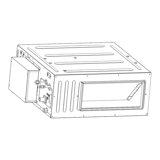
Page 7: Outline Dimension Diagram
Service Manual 3. Outline Dimension Diagram DUCT09HP230V1BD DUCT12HP230V1BD DUCT18HP230V1BD GFH(21)DB-D3DNA1A/I DUCT24HP230V1BD Model 09/12K 32 43/64 29 11/16 11 13/16 31 11/32 27 9/16 18/21/24K 44 31/64 29 11/16 11 13/16 43 7/64 39 3/8 Technical Information... -
Page 8: Refrigerant System Diagram
Service Manual 4. Refrigerant System Diagram Technical Information... -
Page 9: Electrical Part
Service Manual 5. Electrical Part 5.1 Wiring Diagram ●Instruction Symbol Symbol Color Symbol Symbol Color Symbol Name White GREEN COMP Compressor Yellow Brown Grouding wire Blue YEGN Yellow/Green Black Violet Orange ● Outdoor Unit 600007060236 These circuit diagrams are subject to change without notice, please refer to the one supplied with the unit. Technical Information... -
Page 10: Pcb Printed Diagram
Service Manual 5.2 PCB Printed Diagram ● TOP VIEW Interface of dry contact Wired controlller terminal Dispaly Jumper cap Water overflow protection Interface of tube temperature sensor Interface of ambient temperature sensor Water pump Terminal with indoor unit communication Neutral wire terminal Fuse Live wire terminal Neutral wire terminal... -
Page 11: Function And Control
Service Manual 6. Function and Control After putting through the power, air conditioner will give out a sound and indicators on control panel will be on. After that, you operate the air conditioner through remote controller or control panel. 6.1 Introduction of Control Panel 1.1 Display Fig.1 Appearance of wired controller 1.2 Instructions for Related Displayed Symbols... - Page 12 Service Manual Timer on status Gate card pulled-off status or nobody presented status Quiet function Function lock 1.3 Button Grapics Fig. 2 Button graphics 1.4 Function Instructions of Buttons Button name Button Function Set low speed, medium speed,high speed, turbo and auto speed. (1) Set temperature ∧...
-
Page 13: Introduction Of Control Panel
Service Manual 6.2 Introduction of Control Panel 1.Basic function of system (1)Cooling mode (1) Under this mode, fan and swing operates at setting status. Temperature setting range is 16~30 (2) During malfunction of outdoor unit or the unit is stopped because of protection, indoor unit keeps original operation status. (2)Drying mode (1) Under this mode, fan operates at low speed and swing operates at setting status. - Page 14 Service Manual (8)Off-peak energization function: Adjust compressors minimum stop time. The original minimum stop time is 180s and then we change to: The time interval between two start-ups of compressor cant be less than 180+T s(0≤T≤15). T is the variable of controller. Thats to say the minimum stop time of compressor is 180s~195s.
-
Page 15: Part Ⅱ : Installation And Maintenance
Service Manual Part Ⅱ : Installation and Maintenance 7. Notes for Installation and Maintenance Safety Precautions: 10. If the power cord or connection wire is not long enough, please get the specialized power cord or connection wire Important! from the manufacture or distributor. Prohibit prolong the wire by yourself. - Page 16 Service Manual Safety Precautions for Installing and Relocating the Unit: To ensure safety, please be mindful of the following precautions. Warnings 1. When installing or relocating the unit, be sure to keep the refrigerant circuit free from air or substances other than the specified refrigerant.
- Page 17 Service Manual Main Tools for Installation and Maintenance 1. Level meter, measuring tape 2. Screw driver 3. Impact drill, drill head, electric drill 4. Electroprobe 5. Universal meter 6. Torque wrench, open-end wrench, inner hexagon spanner 7. Electronic leakage detector 8.
-
Page 18: Installation Manual
Service Manual 8. Installation Manual Installation procedures Start installation Preparation before installation Read the requirements select installation Prepare tools for electric connection location Select indoor unit Select outdoor unit installation location installation location Install wall-mounting Install the support of outdoor unit (select it according to the actual situation) frame, drill wall holes Connect pipes of indoor... -
Page 19: Preparations For Installation
Service Manual 8.1 Preparations for Installation NOTICE! Product graphics are only for reference. Please refer to actual products. Unspecified measure unit is mm(in.) Please use the supplied standard fittings listed below as instructed. Name Appearance Q'ty Usage Wired Controller To control the indoor unit Drain Hose Assembly To connect with the hard PVC drain pipe To be used for connecting the refrigerant... -
Page 20: Wiring Requirements
Please contact local dealer to arrange professional technicians for the installation. (3) Do not connect power until all installation work is finished. 8.3 Wiring Requirements (1) Power Cord Size and Air Switch Capacity Fuse Model Power Supply Capacity(A) DUCT09HP230V1BD DUCT12HP230V1BD DUCT18HP230V1BD 208/230V-1ph-60Hz GFH(21)DB-D3DNA1A/I DUCT24HP230V1BD Installation and Maintenance... - Page 21 Service Manual (1) Use copper wire only as unit’s power cord. Operating temperature should be within it value. (2) If the power cord is more than 15m (49-1/4 ft.) long, please increase properly the sectional area of power cord to avoid overload, which may cause accident. (3) Above selection requirements: Power cord size is based on BV single-core wire (2~4pc) at 40°C(104°F) Cambient temperature when laying across plastic pipe.
-
Page 22: Installation Instructions
Equip with a inspection hatch after lifting the unit. For the convenience of maintenance, the service port should be on one side of the electric box and below unit’s lower level. Fig 9.1.1 Below are dimensions of A, B, C, etc. for different models: Unit:mm(in.) Model DUCT09HP230V1BD DUCT12HP230V1BD (29-1/8) (19-11/16) (32-11/16) (11-13/16) - Page 23 Service Manual Fig 4.1.3 Fig 4.1.4 2) Insert the M10 expansion bolt into the hole and then knock the nail into the bolt, as shown in fig 4.1.5, and shown in fig 4.1.5, and then remove the pape r pattern. NOTICE! The length of bolt depends on the installation height of the unit, bolts are field supplied.
- Page 24 Service Manual Fig9.1.8 (6) Remove the washer locating plate and then tighten the nut on it. 9.2 Refrigerant Pipe Connection (1) Aim the flaring port of copper pipe at the center of screwed joint and then tighten the flaring nut with hand as shown in fig 9.2.1. (2) Tighten the flaring nut with torque wrench.
- Page 25 Service Manual 9.3.2 Drainage pipe installation (1) Insert the drain hose into the drain hole and tighten it with tapes, as shown in Fig 9.3.2. (2) Tighten the pipe clamp, with the distance between screw nut and hose smaller than 4mm(1/8in .). ①...
- Page 26 Service Manual Unit: mm(in.) Fig 9.3.9 Model DUCT09HP230V1BD DUCT12HP230V1BD DUCT18HP230V1BD 150č 5-7/8G 850F 33-1/2G 800F 31-1/2G GFH(21)DB-D3DNA1A/I DUCT24HP230V1BD (10) Drain pipes should have a downward slope of at least 1%~2%, in order to prevent pipes from sagging, install hanger bracket at intervals of 1000~1500mm(39-3/8~59 in.).
- Page 27 Service Manual 9.3.11 NOTICE! ① ② ③ ④ ⑤ 9.4.1 Shape and Size of Air Outlet and Air-return Opening Unit: mm(in.) Fig 9.4.1 Air Outlet Installation and Maintenance...
- Page 28 Service Manual Fig 9.4.2 Air-return Opening Size of Air Outlet Size of Air-return Opening Model DUCT09HP230V1BD DUCT12HP230V1BD (7-5/8) (17-3/4) (10-3/8) (26) (1-1/8) DUCT18HP230V1BD GFH(21)DB-D3DNA1A/I (7-5/8) (29-9/16) (10-3/8) (37-3/4) (1-1/8) DUCT24HP230V1BD 9.4.2 Installation of Air-out Duct Fig 9.4.5 9.4.3 Fig 9.4.6 Fig 9.4.6...
- Page 29 Service Manual 9.4.7 9.4.7 9.4.4 9.4.8 9.4.9 9.4.9 9.4.8 NOTICE Installation and Maintenance...
-
Page 30: Wiring Work
Service Manual 10. Wiring Work 10.1 10.0.1 3) Shape the tail of wire into ring by needle nose plier, and keep the gauge of ring in accordance with screw. 4) Use the screwdriver for tightening the terminal. (2) The connection of stranded wire (as shown in fig 10.1.2) 1) Strip about 10mm (3/8 in.) insulation of the end of stranded wire by stripping and cutting tool. - Page 31 Service Manual 10.2 Power Cord Connection NOTICE! æ Every unit should be equipped with a circuit breaker for short-circuit and overload protection. During operation, all indoor units connected to the same outdoor unit system must be kept energized status. therwise, the unit can’t operate normally.
-
Page 32: Maintenance
Service Manual 11. Maintenance 11.1 Error Code List Display Method of Indoor Unit Indicator Display (during blinking, ON 0.5s and OFF Dual-8 Malfunction A/C status Possible Causes 0.5s) Code Name Operation Cool Heating Display Indicator Indicator Indicator Possible reasons: During cooling and drying High 1. - Page 33 Service Manual Display Method of Indoor Unit Indicator Display (during blinking, Dual-8 Malfunction ON 0.5s and OFF 0.5s) A/C status Possible Causes Code Name Operation Cool Heating Display Indicator Indicator Indicator When the outdoor unit receive signal of Gathering Gathering refrigerant ,the system will Nominal cooling mode refrigerant be forced to run under cooling mode for...
- Page 34 Service Manual Display Method of Indoor Unit Indicator Display (during blinking, ON 0.5s and OFF Dual-8 Malfunction A/C status Possible Causes 0.5s) Code Name Operation Cool Heating Display Indicator Indicator Indicator Decrease Overload or temperature is too high; frequency All loads operate normally, while Refrigerant is insufficient;...
- Page 35 Service Manual Display Method of Indoor Unit Indicator Display (during blinking, ON 0.5s and OFF Dual-8 Malfunction A/C status Possible Causes 0.5s) Code Name Operation Cool Heating Display Indicator Indicator Indicator Compressor intermediate Showing during middle cooling or middle frequence in heating test test state Overcurrent...
- Page 36 Service Manual Display Method of Indoor Unit Indicator Display (during blinking, ON 0.5s and OFF Dual-8 Malfunction A/C status Possible Causes 0.5s) Code Name Operation Cool Heating Display Indicator Indicator Indicator 1. Bad contact of DC motor feedback terminal. 2. Bad contact of DC motor Internal motor Internal fan motor, external fan motor, compressor and control end.
- Page 37 Service Manual Display Method of Indoor Unit Indicator Display (during blinking, ON 0.5s Dual-8 Malfunction and OFF 0.5s) A/C status Possible Causes Code Name Operation Cool Heating Display Indicator Indicator Indicator During cooling and drying Malfunction of operation, compressor will stop phase current while indoor fan will operate;...
- Page 38 Service Manual If malfunction occurs,corresponding code will display and the unit will resume normal until protection or malfunction disappears. Installation and Maintenance...
- Page 39 Service Manual Analysis or processing of some of the malfunction display: 1. Compressor discharge protection Possible causes: shortage of refrigerant; blockage of air filter; poor ventilation or air flow short pass for condenser; the system has noncondensing gas (such as air, water etc.); blockage of capillary assy (including filter); leakage inside four-way valve causes incorrect operation;...
-
Page 40: Troubleshooting For Main Malfunction
Service Manual 11.2 Troubleshooting for Main Malfunction Indoor unit: 1. Malfunction of Temperature Sensor F1, F2 Main detection points: ● Is the wiring terminal between the temperature sensor and the controller loosened or poorly contacted? ● Is there short circuit due to trip-over of the parts? ●... - Page 41 Service Manual 2. Malfunction of Blocked Protection of IDU Fan Motor H6 Start Turn the fan blades by hand under power-off condition Adjust the motor and blade Whether the fan blades assembly so that rotor can run can run smoothly? smoothly.
- Page 42 Service Manual 3. Malfunction of Protection of Jumper Cap C5 Main detection points: ● Is there jumper cap on the mainboard? ● Is the jumper cap inserted correctly and tightly? ● The jumper is broken? ● Detectioncircuit of the mainboard isdefined abnormal? Malfunction diagnosis process: Start Appearance of the...
- Page 43 Service Manual 4. Water overflow protection E9 Malfunction diagnosis process: Error display Check whether Whether the voltage Replace the main board there is water of liquid level switch of indoor unit overflow terminal is correct? Check the liquid level switch Whether the voltage Whether the drain Replace the main board...
-
Page 44: Maintenance Method For Normal Malfunction
Service Manual 11.3 Maintenance Method for Normal Malfunction 1. Air Conditioner Cant be Started Up Possible Causes Discriminating Method (Air conditioner Status) Troubleshooting Confirm whether its due to power failure. If yes, No power supply, or poor After energization, operation indicator isnt bright wait for power recovery. - Page 45 Service Manual 4. ODU Fan Motor Cant Operate Possible causes Discriminating method (air conditioner status) Troubleshooting Connect wires according to wiring diagram to Wrong wire connection, or poor Check the wiring status according to circuit make sure all wiring terminals are connected connection diagram firmly...
-
Page 46: Exploded View And Parts List
Service Manual 12. Exploded View and Parts List DUCT09HP230V1BD DUCT12HP230V1BD The component picture is only for reference; please refer to the actual product. Installation and Maintenance... - Page 47 Service Manual Part Code Description DUCT09HP230V1BD DUCT12HP230V1BD Product Code CF022N1420 CF022N1400 Wired controlller 30564103 30564103 Drain Hose Sub-Assy 05232050 05232050 Temperature Sensor 390000592 390000592 Temperature Sensor 390000454 390000454 Right Side Plate Assy 01315200148 01315200148 Hook 02112466 02112466 Centrifugal Fan Assy...
- Page 48 Service Manual DUCT18HP230V1BD GFH(21)DB-D3DNA1A/I DUCT24HP230V1BD 14 15 The component picture is only for reference; please refer to the actual product. Installation and Maintenance...
- Page 49 Service Manual Part Code Description DUCT18HP230V1BD GFH(21)DB-D3DNA1A/I DUCT24HP230V1BD Product code CF022N1390 CF022N1410 CF022N1430 Air in Frame Assy 017026000002 017026000002 017026000002 Filter Sub-Assy 111001000045 111001000045 111001000045 Propeller Housing(Upper) 26905200078 26905200078 26905200078 Centrifugal Fan 10455200003 10455200003 10455200003 Brushless DC Motor 15705200016 15705200016 15705200016 Propeller Housing(Upper) 26905200078...
-
Page 50: Removal Procedure
Service Manual 11. Removal Procedure 09/12/18/21/24K Motor and fan Precondition: The power supply has been disconnected. Step Diagram Operation Procedure ●Use a screwdriver tounscrew the electric box cover. 1.Remove ●Remove from the master board line connecting to the motor. the line connecting to the motor and remove the tie. - Page 51 Tel: (+86-756) 8522218 Fax: (+86-756) 8669426 U.S. E-mail: info@twclimate.com U.S. Product Information: www.greecomfort.com HONG KONG GREE ELECTRIC APPLIANCES SALES LIMITED Add: Unit 2612,26/F.,Miramar Tower 132 Nathan Road,TST,Kowloon,HK Tel: (852) 31658898 Fax: (852) 31651029 For product improvement, specifications and appearance in this manual are subject to change without prior notice.
Need help?
Do you have a question about the DUCT09HP230V1BD and is the answer not in the manual?
Questions and answers