Table of Contents
Advertisement
Advertisement
Table of Contents

Related Manuals for Gree FHBQ-D8-K


Summary of Contents for Gree FHBQ-D8-K
- Page 1 Energy-Recovery Ventilation System Service Manual ( GC201202-I )
-
Page 2: Table Of Contents
Energy-Recovery Ventilation System Service Manual CONTENTS PRODUCT ........................2 1 MODELS LIST ....................2 2 NOMENCLATURE....................2 3 FEATURES......................3 4 PRODUCT DATA....................3 5 PIPING DIAGRAM....................5 CONTROL........................7 1 OPERATION FLOWCHART.................7 2 MAIN LOGIC......................8 3 WIRED REMOTE CONTROLLER...............8 INSTALLATION........ - Page 3 Energy-Recovery Ventilation System Service Manual PRODUCT PRODUCT...
-
Page 4: Product
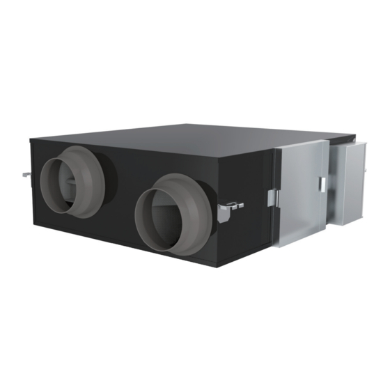
Energy-Recovery Ventilation System Service Manual PRODUCT 1 MODELS LIST 1.1 Outdoor Unit External static Model Product code Air flow (m Power supply Appearance pressure (Pa) 50/100 EH01100030 FHBQ-D8-K(D) 40/85 (EH01100100) 30/65 220V-50Hz (208-230V-60Hz) 820/1000 EH01100040 FHBQ-D10-K(D) 620/750 (EH01100080) 500/600 EH01100050... -
Page 5: Features
Healthy, energy-saving, simple and reliable fresh-air system and equipment has been the focus for engineers and users. Gree energy recovery ventilation system has solved this problem. This kind of system has two-way air exchange function so that the change of indoor temp is little during air exchange. The indoor air can be efficiently filtered by the air filter. - Page 6 Energy-Recovery Ventilation System Service Manual Gross weight (kg) 66.5 66.5 20'GP Loading quantity 40'GP 40'HQ Standard wired remote controller Z4E35M Z4E35M Model FHBQ-D15-M(D) FHBQ-D20-M(D) FHBQ-D30-M Power supply 380VAC 3N 50Hz (208-230VAC 3N 60Hz) Air flow volume (m 1500 1800/2000 2800 External statics pressure (Pa) 50/150 Temperature exchange...
-
Page 7: Piping Diagram
Energy-Recovery Ventilation System Service Manual 4.2 Electrical Data Power supply Fan motor Max. fuse breaker size Min. disconnect size Model V, Ph, Hz FLA Each Amperes Amperes FHBQ-D8-K(D) 1.0A×2 3.25A 2.25A 220V-50Hz (208V-230V-60Hz) FHBQ-D10-K(D) 1.0A×2 3.25A 2.25A FHBQ-D15-M(D) 1.4A×2 4.55A 3.15A... - Page 8 Energy-Recovery Ventilation System Service Manual CONTROL CONTROL...
-
Page 9: Control
Energy-Recovery Ventilation System Service Manual CONTROL 1 OPERATION FLOWCHART CONTROL... -
Page 10: Main Logic
Energy-Recovery Ventilation System Service Manual 2 MAIN LOGIC 2.1 Auto Mode Detect the temperature indoor and outdoor for durative a period of time. (1) The system will operate under by pass mode according to temperature and temperature difference between room and outdoors is little in transient season. - Page 11 Energy-Recovery Ventilation System Service Manual ■Turn On / Off the Unit (1) Press ON/OFF button to start the unit. (Fig.2) (2) Press ON/OFF button once again to stop the unit. (3) Under the “Off” status, pressing the “Mode” key for 5 seconds can activate the memory function upon power failure, In this case, when 01 is displayed at the temperature set point area, it indicates the memory function has been activated.
- Page 12 Energy-Recovery Ventilation System Service Manual As shown in the figure 4, under discharge or supply air modes, by pressing the “Fan” key, the fan speed will switch between low and high speed, which is also unavailable for FHBQ-D15 and FHBQ-D20. Fig.4 ■Humidity Adjustment (Fig.5) For the unit with humidifying function, pressing the “▲”...
- Page 13 Energy-Recovery Ventilation System Service Manual ■Reset/ Switch Function Setting (Fig.6) When it is required to clean the unit, the beeper will raise an alarm for 30s. In this case, by pressing the “Reset” key for five seconds, the runtime for cleaning will become zero, the beeper will stop and the cleaning symbol will disappear. When the unit is turned on, by pressing the “Timer”...
- Page 14 Energy-Recovery Ventilation System Service Manual ■Timer Setting (Fig.8) In off status of the unit, timer on can be set and in on status, timer off, energy-saving on and energy –saving off and air clear can be set. Press Timer button into timer setting status. TIMER,Hr and letters corresponding setting will blink. (E.g.during timer off setting, Timer,Hr and OFF will flash).In this case, the user can press ▲or ▼to increase or decrease setting time.
- Page 15 Energy-Recovery Ventilation System Service Manual ■Address Setting Fig.9 When the unit is off, by pressing the “Mode” and “Switch” keys at the same time for five seconds, it is able to set the address of the control (1~16). At this point, address can be increased or decreased by pressing the “▲” or “▼” key. This address intends to distinguish different dampers.
- Page 16 Energy-Recovery Ventilation System Service Manual Bottom panel dimension and installation dimension 3.3 Installation Locate the installation position firstly, and then reserve a groove or hole for embedding of communication wire according to its dimension. If wired controller and indoor communication wire are mounted visibly, 1 # PVC pipe can be used and corresponding grooves should be set in the wall.
- Page 17 Energy-Recovery Ventilation System Service Manual Name Remarks Wall The appearance of the controller Underplate of wire controller should be subject to entity. Screw M4X10 Controller panel CONTROL...
- Page 18 Energy-Recovery Ventilation System Service Manual INSTALLATION...
-
Page 19: Installation
Energy-Recovery Ventilation System Service Manual INSTALLATION 1 DIMENSION DATA Fresh air inlet Fresh air outlet Room air outlet Room air inlet Uint: mm Model FHBQ-D8-K(D) 1016 FHBQ-D10-K(D) 1016 FHBQ-D15-M(D) 1215 1159 1210 1262 FHBQ-D20-M(D) 1215 1159 1210 1262 Electric Flange dimension... -
Page 20: Installation Site
Energy-Recovery Ventilation System Service Manual 2 INSTALLATION SITE Room air outlet Fresh air inlet Service space Fresh air outlet Room air inlet During installation, the two ducts (fresh air inlet and indoor air outlet) outside the room must be installed with anti- condensate and heat insulating materials, and the ones inside the room should also be installed with them if temperature and humidity in the ceiling is high. -
Page 21: Cautions For Installation
Energy-Recovery Ventilation System Service Manual Inner steer bar φ16hanger Pitch >1/30 Ceiling Return air vent Diffuser Room air inlet Outdoor Indoor Air duct muffler Room air outlet Fresh air inlet Air duct muffler Vent for inspection and repair 4 CAUTIONS FOR INSTALLATION (1) Never lay wires, cables and pipes with toxic, inflammable or explosive gas or liquid in the duct. -
Page 22: Electric Wiring Work
Energy-Recovery Ventilation System Service Manual 5 ELECTRIC WIRING WORK 5.1 Wiring Principle ■Layout of Wires (1) Layout of wires should accord with national wiring criteria. (2) The power supply must be with rated voltage and special for AC. (3) The power supply should be reliable to prevent terminals from being stressed. Never pull the power cord forcibly. (4) The line width of power cord must be large enough. - Page 23 5.3 Specification of Power Supply Wire and Air Switch Capacity of air Min. sectional area of Min. sectional area of Applied models Power supply switch (A) earthing wire (mm power cord (mm 220V-50Hz FHBQ-D8-K(D) (208V-230V-60Hz) 220V-50Hz FHBQ-D10-K(D) (208V-230V-60Hz) 380V 3N-50Hz FHBQ-D15-M(D) (208V-230V 3N-60Hz) 380V 3N-50Hz...
- Page 24 Energy-Recovery Ventilation System Service Manual MAINTENANCE...
-
Page 25: Maintenance
Energy-Recovery Ventilation System Service Manual MAINTENANCE 1 TROUBLE TABLE Error Error code Logic Communication between the main board and the wire remote Communication error controller is in trouble. Something is wrong with temp sensor or the temperature is Indoor temp sensor error overstep the range of the temp sensor. -
Page 26: Flow Chart Of Trouble Shooting
Energy-Recovery Ventilation System Service Manual 2 FLOW CHART OF TROUBLE SHOOTING... - Page 27 Energy-Recovery Ventilation System Service Manual 3 WIRING DIADRAM External wiring figure of the unit(If this one is different from wiring figure of junction box, take the wiring box of junction box as standard) . (1) Model: FHBQ-D8-K(D)/FHBQ-D10-K(D) (2) Model: FHBQ-D15-M/FHBQ-D20-M...
- Page 28 Energy-Recovery Ventilation System Service Manual (3) Model:FHBQ-D15-D/FHBQ-D20-D.
-
Page 29: Disassembly And Assembly Of Main Parts
Energy-Recovery Ventilation System Service Manual (4) Model: FHBQ-D30-M. Exhaust GNRD YE GN RD POWER Blower Motor Exchange YEGN YEGN Motor Controlling switch (back side) Note: 1.Press "ON" or "Exchange",L is connected with L1,disconnected with L2; 2.Press "OFF" or "Exhaust", L is connected with L2, disconnected with L1; 3.The broken line part is connected by user. - Page 30 Energy-Recovery Ventilation System Service Manual 4.1 Main parts introduce Service door’s teardown Image Discharge the two bolts on the right of the Service door, and then take down the buckle. Bolt Electric box’s teardown Image Capacitance Remove the two bolts and then circumgyrate the Electric Box to open it.
-
Page 31: Exploded Views And Part List
Remove the bolt that used to fix the fan and side panel. Bolt 5 EXPLODED VIEWS AND PART LIST (1) Exploded view for models: FHBQ-D8-K(D); FHBQ-D10-K(D); FHBQ-D15-M(D);FHBQ-D20-M(D) 1)FHBQ-D8-K(D) (EH01100030,EH01100100) Name Quantity Code Sponge 1( Left Side Plate) - Page 32 Energy-Recovery Ventilation System Service Manual Name Quantity Code Electric Box Assy 01396160 Sub-assy of Right Side Plate 01311125 Flange Sub-assy 26906056 Foam Assy 1 12311103 sponge(Side of Bottom Plate) 12201141 By-pass assy 04631124 Filter Sub-assy 1112800101 Total heat exchange core assy + sponge 4901890206+12201142 Foam Assy 2 12311102...
- Page 33 Energy-Recovery Ventilation System Service Manual 3)FHBQ-D15-M(D) (EH01100050,EH01100110) Name Quantity Code Sponge 1( Left Side Plate) 12201145 Sponge 2( Left Side Plate) 12201146 Assy of Left Side Plate 01311129 Assy of overhauling door 01391136 Door Holder 02208901 Base Plate Assy 02225200035 Retaining Plate Assy 01841110 Rubber Sheet...
- Page 34 Energy-Recovery Ventilation System Service Manual (2) Exploded view for model: FHBQ-D30-M(D)
- Page 35 Energy-Recovery Ventilation System Service Manual FHBQ-D30-M(D)(EH01100070) Parts List Name Quantity Code Front side plate assy 1 01318912 Assy of overhauling door 01398904 Electric Box Assy 01396168 Filter Sub-ass 11128001 Front side plate assy 2 01316080 Hanger crossbeam 01871226 Bottom plate assy 02228904 Rubber gasket 76018401...
- Page 36 JF00300198...
Need help?
Do you have a question about the FHBQ-D8-K and is the answer not in the manual?
Questions and answers