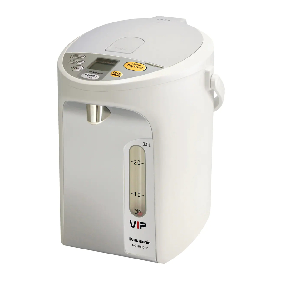
Panasonic NC-HU301P Service Manual
Electric thermo pot
Hide thumbs
Also See for NC-HU301P:
- Operating instructions manual (52 pages) ,
- Operating instructions manual (32 pages) ,
- Service manual (42 pages)
Advertisement
Service Manual
Specifications
Power Supply
Power Consumption
Rated
(approx.)
Boiling
Keep Warm
Average power
consumption during
keep warm
Capacity (approx.)
Dimension (approx.) (W x D x H)
Weight (approx.)
Thermal regulation
Rotating base
Thermal fuse
Power cord
Hot water supply device specifications
Hot water supply method
Current volume adjustment range
Operation method
Pump-lock
Hot water pump
Power consumption
Rated duration
Additional function : Dechlorination, keep warm (98, 90, 80), Energy saving timer 4, 6, 8 and 10 hours),
Overheating protection, Citric acid cleaning.
This service information is designed for experienced repair technicians only and is not designed for use by the general public.
It does not contain warnings or cautions to advise non-technical individuals of potential dangers in attempting to service a product.
Products powered by electricity should be serviced or repaired only by experienced professional technicians. Any attempt to service
or repair the product or products dealt with in this service information by anyone else could result in serious injury or death.
Panasonic
All manuals and user guides at all-guides.com
NC-HU301P
Taiwan
Hong Kong
Thailand
Vietnam
110V
220V
220V
925W
875W
875W
69W
112W
112W
°
98 C
°
90 C
°
80 C
Average power consumption per hour for keep warm status.
(Conditions : Room temperature, water temperature 20
24.8 x 31.0 x 29.0
Boiling : Relay, Thyristor
Warming : Thyristor
Electronic lock system (Locked in 10 sec. after switching "Dispense")
WARNING
All rights reserved. Unauthorized copying and distribution
is a violation of law.
ORDER NO. PHAT080502C3
(Revision : Aug. 2010)
Electric Thermo Pot
NC-HU301P
NC-HU401P
Noble Champaign(N), Silver White(SW)
Thailand, Taiwan, Hong Kong
Singapore, Malaysia, USA/Canada
Singapore
USA/CND
RUS/UKR
220V
230V
120V
220V
875W
955W
925W
875W
112W
133W
83W
112W
18Wh
16Wh
10Wh
°
C
with rated water volume)
3.0L
3.0kg
Boiling : Relay, Thyristor
Can rotate 360 ° with the power cord
157
° C
Approx. 1 m
Electric pump
54ml/sec (Constant)
Push switch
1.5W (DC commulator motor)
3 minutes
© Panasonic Home Appliances (Thailand) Co., Ltd. 2008.
Product Color
Destination
Vietnam, Russia/Ukrain
NC-HU401P
Taiwan
Hong Kong
USA/CND
Malaysia
110V
220V
120V
240V
925W
875W
925W
1040W
69W
112W
83W
122W
19Wh
17Wh
15Wh
4.0L
24.8 x 31.0 x 33.9
3.2kg
Advertisement

Subscribe to Our Youtube Channel
Related Manuals for Panasonic NC-HU301P


Summary of Contents for Panasonic NC-HU301P
-
Page 1: Specifications
Panasonic © Panasonic Home Appliances (Thailand) Co., Ltd. 2008. All rights reserved. Unauthorized copying and distribution is a violation of law. -
Page 2: Table Of Contents
All manuals and user guides at all-guides.com NC-HU301P, NC-HU401P Contents Page 1. Specifications...............................1 2. Cautions for safe repair work ..........................2 3. Part Names and Operation ..........................3 4. Reassembling and Assembling Procedure ......................20 5. Wiring diagram ..............................33 6. Parts location and parts list ..........................36... -
Page 3: Part Names And Operation
All manuals and user guides at all-guides.com NC-HU301P, NC-HU401P 2. Part Names and Operation Operation panel • If the protective film is still covering the surface of the operation panel, peel it off before using the operation panel. Steam vent... - Page 4 All manuals and user guides at all-guides.com NC-HU301P, NC-HU401P LED symbol for this instruction show as below. 3. Problems Checking Lighted Please follow check operating detail bellow, before start to check Blink the problems. 3.1. Thermo Pot Performance Test Mode Instructions 1.
- Page 5 All manuals and user guides at all-guides.com NC-HU301P, NC-HU401P 3.1.2. Reboiling and keep warm test Operating details If press LONG BOIL/REBOIL pad once. How to operate 1. Long boil/Reboil LED will be lighted and start to boil water. 1. Set Keep Warm.
- Page 6 All manuals and user guides at all-guides.com NC-HU301P, NC-HU401P 3.1.3. Pour out test (Electric pump type) How to operate Operating detail 1. Pour hot water into Container. 1. LCD monitor will display as picture below. 2. Supply with electric power.
- Page 7 All manuals and user guides at all-guides.com NC-HU301P, NC-HU401P 3.3. Relation of elapsed time and possible water pouring volume (Reference only) 4.0 L hour 3.0L hour 9.75hr 9.75hr After 4.25h After 1h 4.25h Possible continuous pouring volume when changed to cordless from Warm Keep State.
- Page 8 All manuals and user guides at all-guides.com NC-HU301P, NC-HU401P 3.4 Check points 3.4.1. Picture is the case of 3.0L To peg frame Blue Blue White Orange Boiling heater (Between • Orange Approx.58 Ω) Keep warm heater • (Between Orange Approx.432 Ω)
- Page 9 All manuals and user guides at all-guides.com NC-HU301P, NC-HU401P 3.4.2. List of lead wire color HU all series Thermal fuse comp. Lead wire A Series SU1/HU1/MU1 HU1P(HK) HU1P(TWN) HU2/MU2 HU1P(USA) HU1P(RUS/UKR) HU301P Model SU221 SU301 SU401 HU301P HU401P HU301P HU401P HU222...
- Page 10 All manuals and user guides at all-guides.com NC-HU301P, NC-HU401P 3.5. Failure Diagnostics Chart 3.5.1. No power (No indication, no pouring) The items in the Check correspond to those shown in Check Point on P.9. c i t Thermal fuse Comp.
- Page 11 All manuals and user guides at all-guides.com NC-HU301P, NC-HU401P 3.5.5. Long Boil/Reboil LED and 98 keep warm LED are lighted up alternately. (LCD display : H1) The items in the Check correspond to those shown in Check Point on P.9.
- Page 12 All manuals and user guides at all-guides.com NC-HU301P, NC-HU401P 3.6. Operating and LCD Monitor Display Example 3.6.1. Boiling (If select keep warm at 98) Power ON (Boiling) Press Select pad to 98 Boiling detection after 2 minutes (Long Boil/Reboil LED:Lighted) (Long Boil/Reboiling &...
- Page 13 All manuals and user guides at all-guides.com NC-HU301P, NC-HU401P 3.6.3. Boiling (IF specify Long Boil) Power ON (Boiling) Boiling detection after 2 minutes (Long Boil/Reboil LED : Lighted) (Long Boil/Reboil LED : Blink) (Long Boil/Reboil LED : OFF) Press Long Boil/Reboil Extend boiling approx.
- Page 14 All manuals and user guides at all-guides.com NC-HU301P, NC-HU401P 3.6.5. Keep warm (When want to reboil from 90 Keep warm) Boiling detection after 2 minutes (Long Boil/Reboil LED : Blink) (Long Boil/Reboil LED : OFF) Press Long Boil/Reboil Extend boiling approx.
- Page 15 All manuals and user guides at all-guides.com NC-HU301P, NC-HU401P 3.6.8. Timer Mode (If 90 Keep warm) Boiling mode (Heater turns off, no boiling) (Long Boil/Reboiling LED : Lighted) Power ON Boiling mode (Long Boil/Reboiling LED : OFF) Displayed by the hour.
- Page 16 All manuals and user guides at all-guides.com NC-HU301P, NC-HU401P 3.6.10. If Automatic keep warm (If 98 Keep warm) (Long Boil/Reboiling LED : OFF) (Long Boil/Reboiling LED : OFF) (Long Boil/Reboiling LED : OFF) Unused hours Come at set temperature (No boiling) If temperature setting of 90 or 80, it switches to Keep warm when reaches at 90 or 80 simultaneously without boiling.
- Page 17 All manuals and user guides at all-guides.com NC-HU301P, NC-HU401P 3.7. About “Automatic saving” function • This unit remembers the daily use pattern, the hours this unit is used or not, after the power is supplied at first. Refer to P.18 for the storage of the use pattern, the hours this unit is used or not.
- Page 18 All manuals and user guides at all-guides.com NC-HU301P, NC-HU401P 3.7.3. Cancel of “Automatic Saving” If “Timer” pad is pressed 5 times, following will be performed. “Automatic” is displayed on LCD, and performs either mode of “Unused hours” or “Used hours”.
- Page 19 All manuals and user guides at all-guides.com NC-HU301P, NC-HU401P NC-HU301P, NC-HU401P — 19 —...
-
Page 20: Reassembling And Assembling Procedure
All manuals and user guides at all-guides.com NC-HU301P, NC-HU401P 4. Reassembling and Assembling Procedure Caution [Below figure shows the case] Attention, Be careful for injuries by the Please assemble in the reverse sequence referring to end face of metal portions Assembling points. - Page 21 All manuals and user guides at all-guides.com NC-HU301P, NC-HU401P 4.2. Body 1. Refasten binding band (Refer to Fig-2) 2. Remove each lead wire hook to the body while removing the body. 3. Remove the body upward. (Refer to Fig-3) Binding band...
- Page 22 All manuals and user guides at all-guides.com NC-HU301P, NC-HU401P 4.3. Control Unit A comp. (Peg flame) 3.5x12 bind tapping screw Caution When touching the control unit, or may touch it, ground the human body, clothes, working table etc. with several mage ohm resister,...
- Page 23 All manuals and user guides at all-guides.com NC-HU301P, NC-HU401P 4.4. Electric pump, Bottom insulator B 1. Remove a screw fixing electric pump. 2. Pull out the water pipe packing A comp. from electric Bottom insulator B Electric pump 4x8 pan head pump.
- Page 24 All manuals and user guides at all-guides.com NC-HU301P, NC-HU401P 4.6. Control unit B comp. (Display portion) 1. Disassemble Casing A comp. 2. Take off 2 screws (Refer Fig-10) 3. Disassemble Holder B. (Lift up) 4. Remove Name C. 5. Disconnect lead wire E comp. CN12.
- Page 25 All manuals and user guides at all-guides.com NC-HU301P, NC-HU401P 4.7. Insulation panel A comp. Point when working 1. Remove Heat shield material A comp. from Container comp. (Directly remove upward while thermistor comp., • Be careful not to scratch Heat shield material A comp.
- Page 26 All manuals and user guides at all-guides.com NC-HU301P, NC-HU401P 4.9. Upper trame Point when assembling 1. Remove cover 2. Remove water out pipe cover • Set the dowel of Container comp. between 2 long ribs 3. Remove Container gasket (hinged side) of Dispensing spout comp. and assemble it.
-
Page 27: Front Panel
All manuals and user guides at all-guides.com NC-HU301P, NC-HU401P 4.11. Front panel 1. Take out 2 screws. 2. Turn over the body. 3. Release the 2 hooks by pushing with needle-nose plier. Points when working • Wear gloves when disassemble the front panel. - Page 28 All manuals and user guides at all-guides.com NC-HU301P, NC-HU401P 4.12. Dispensing spout cover Points when assembling 1. Press both sides of Dispensing spout cover slightly and remove from front panel • Set convex A on dispensing spout cover into square hole B.
- Page 29 All manuals and user guides at all-guides.com NC-HU301P, NC-HU401P 4.14. Lid comp and inner lid 1. Remove the 3 screws. 2. Remove the Inner lid. 4 × 10 Tapping Screws (Stainless) Inner lid Seal packing B Lid (Comp) Disassembly-20 4.15. Lid A and lid cover comp.
- Page 30 All manuals and user guides at all-guides.com NC-HU301P, NC-HU401P 4.16. Locking spring A 1. Remove Locking spring with longnose plier Lock spring B Fig-20 4.17. Lock knob B, Lock spring B 4.18. Insulation panel B 1. Remove Lock knob B pressing toward arrow direction.
- Page 31 All manuals and user guides at all-guides.com NC-HU301P, NC-HU401P 4.19. Check after assembly After assembly, check for any water leaks, insulation resistance, dielectric strength, and performance, with power applied. The insulation resistance: Shall be 2MΩ or more when measured with a 500 VDC megger. (Measuring point: Between the 2...
- Page 32 All manuals and user guides at all-guides.com NC-HU301P, NC-HU401P 4.21. Overall Performance Test Caution Be careful for scald by hot water while testing 4.21.1. Temperature test while Keep warm (98 Keep warm setting) 1. Pour rated volume of water into container and boil it. (Check it is boiled.) 2.
-
Page 33: Wiring Diagram
All manuals and user guides at all-guides.com NC-HU301P, NC-HU401P 5. Wiring diagram 5.1. Connection diagram Control unit A comp. Control unit B comp. (bottom) (operation) Thermistor assy. Peg frame Container comp. Keep warm Heater :112W Main Heater : 833W Thermal fuse comp. - Page 34 All manuals and user guides at all-guides.com NC-HU301P, NC-HU401P 5.2. Actual Wiring Diagram (in case of 3.0L) Caution Return to original wiring after repair. Lead wires touch to the surface of parts, and may cause fault or power shock. Boiling Heater (832.6-910W)
- Page 35 All manuals and user guides at all-guides.com NC-HU301P, NC-HU401P 5.3. Actual Wiring Diagram (in case of 4.0L) Caution Return to original wiring after repair. Lead wires touch to the surface of parts, and may cause fault or power shock. Boiling Heater (990.9W)
-
Page 36: Parts Location And Parts List
All manuals and user guides at all-guides.com NC-HU301P, NC-HU401P 6. Parts Location and Parts List 6.1. Development 10.1 25 26 — 36 —... - Page 37 All manuals and user guides at all-guides.com NC-HU301P, NC-HU401P 6.2. REPLACEMENT PARTS LIST Important safety notice : Components identified by mark have special characteristics important for safety. When replacing any of these components, use only manufacturer’s specified part. Part List REF.
- Page 38 All manuals and user guides at all-guides.com NC-HU301P, NC-HU401P REF. PART NAME PART NO. SAFETY HU301P HU401P TAIWAN HONG KONG THAILAND VIETNAM SINGAPORE USA/CSD Malaysia RUS/UKR THERMAL FUSE COMP. APS01B62810U APS01H62810U APS01A62820U APS01B62910U APS01H62910U ...
- Page 39 All manuals and user guides at all-guides.com NC-HU301P, NC-HU401P REF. PART NAME PART NO. SAFETY HU301P HU401P TAIWAN HONG KONG THAILAND VIETNAM SINGAPORE USA/CSD Malaysia RUS/UKR APY01B628-S0 GUAGE COVER APY01H628-S0 APY01H628-N2 APY01K628-S4 APY01B629-S0 APY01H629-S0 ...
- Page 40 All manuals and user guides at all-guides.com NC-HU301P, NC-HU401P 6.3. Packing Instruction Manual Power Activated Carbon Case Set Cord Pad B Protection Bag Pad A Pad C Inner Box — 40 —...
- Page 41 All manuals and user guides at all-guides.com NC-HU301P, NC-HU401P Detail Change Notice REVISION ITEM NO. PAGE DETAIL REMARK Jun. 2010 Add Picture No. 50 Add Activated Carbon Case Set Add Part Name, Part No. and Q’ty Revise Part Name of Active Charcoal Filter Aug.
Need help?
Do you have a question about the NC-HU301P and is the answer not in the manual?
Questions and answers