Table of Contents
Advertisement
Quick Links
Advertisement
Table of Contents

Related Manuals for ARAG Skipper LT


Summary of Contents for ARAG Skipper LT
- Page 1 Satellite navigator 467020 Software rel. 2.0X inStallation, uSe and maintenance...
-
Page 2: Legend Symbols
This manual is an integral part of the equipment to which it refers and must accompany the equipment in case of sale or change of ownership. Keep it for any future reference; ARAG reserves the right to modify product specifications and instructions at any moment and without notice. -
Page 3: Table Of Contents
4 Contents of the package ..................................5 5 Installation ....................................... 6 Introduction ..................................... 6 System configuration ..................................6 General precautions for locating the Skipper LT and cable runs ....................6 Overall dimensions ..................................7 Skipper LT navigator position ................................7 Locating the antenna ..................................8 Electrical connections - general diagram ............................ - Page 4 CONTENTS 9 Maintenance / diagnostics / repairs ..............................50 Error messages .................................... 50 Troubleshooting .................................... 50 10 Technical data ....................................... 51 10.1 Displayed data and relevant units of measurement ........................51 11 End-of-life disposal....................................52 12 Guarantee terms....................................52...
-
Page 5: Product Description
INTRODUCTION Product descriPtion SKIPPER LT is a satellite navigation system that can be used for agricultural spraying and navigation applications, once connected to the external GPS antenna. intended use This device is designed to work on agricultural machinery for crop spraying applications. The machine is designed and built in compliance with EN ISO 14982 standard (Electromagnetic compatibility - Forestry and farming machines), harmonized with 2004/108/EC Directive. Skipper LT is not a road navigator and should only be used on agricultural land. Precautions • Do not aim water jets at the equipment. • Do not use solvents or fuel to clean the case outer surface. • Do not clean equipment with direct water jets. • Comply with the specified power voltage (12 Vdc). • If doing arc-welding, disconnect the connectors from Skipper LT and disconnect its power cables. • Only use ARAG genuine spare parts and accessories. -
Page 6: Installation
5.1 Introduction Installation of the Skipper LT system does not require specialist knowledge. We recommend however that this be done by a qualified technician in as much as the installation also requires electrical connections to be made. ARAG IS NOT LIABLE FOR ANY DAMAGE CONSEQUENT ON INSTALLATION BY UNQUALIFIED PERSONS. IF CASE OF DAMAGE TO THE SYSTEM CAUSED BY INCORRECT INSTALLATION OR CONNECTIONS, THE WARRANTY IS AUTO- MATICALLY VOIDED. -
Page 7: Overall Dimensions
Before positioning the satellite navigator, carefully read all information given under par. 5.3 - General precautions for locating the Skipper LT and cable runs. Position Skipper LT centrally into the cabin so that it does not impair driving visibility while allowing data check during treatment. 1) Position the mounting rail in the cabin using the suitable supplied screws, in a position where the navigator is in view and within hands reach, but away from any moving organs. -
Page 8: Locating The Antenna
INSTALLATION Locating the antenna The user must position the GPS antenna as indicated in this manual and make sure that the modified vehicle height does not lead to an impact with any obstacle. Installing the antenna: Installation of the antenna on agricultural equipment must observe certain basic requirements: • it must be installed on the highest point of the machine (including trailer): the skywards reception angle must be as unobstructed as possible. Fig. - Page 9 INSTALLATION Antenna fastening: The antenna has a magnetic base and should be positioned on a flat metal surface (e.g. farm machine roof). In case of plastic roof, use the supplied metal plate and sticker. Remove one of the protective films from the sticker and stick it onto the metal plate. Then remove the other protective film and position the plate where the antenna is being fitted after cleaning the whole area.
-
Page 10: Electrical Connections - General Diagram
Automotive fuse - 3 A e Treatment status signal +12 Vdc (from main control valve) Connection to the GPS antenna Only use the specific ARAG GPS antenna to be used in connection with SKIPPER LT. ARAG shall not be held liable for loss or damage due to use of different types of antenna. Before making the connection, carefully read par. 4.3 - General precautions for locating the SKIPPER LT and cable runs. Connect the external GPS antenna to Skipper LT. The connection points are given in par. 4.7 - Electrical connections - general diagram. -
Page 11: Treatment Status Signal
Treatment status signal If the machine is equipped with a treatment control, such as a switch on the control valve, the SKIPPER LT can be connected to a corresponding treatment status signal, so that it receives a +12 Vdc signal directly from the control itself when treatment starts. -
Page 12: Programming
Fig. 12 Fig. 11 first start-uP of the deVice Upon its first start-up, after showing the software version, Skipper LT directly opens the page for setting the language (Fig. 13). Enter value and proceed to the normal switch-on procedure (Fig. 14). -
Page 13: Switching Off
PROGRAMMING normaL sWitch-on Procedure After showing the software version, Skipper LT displays the follow- Continue last job? ing message (Fig. 15). Button allows you to continue the last job done before switching off, using the active machine. Fig. 14 Button moves on to a new job without saving the last one done before switch-off. -
Page 14: Using The Programming Keys
PROGRAMMING 6.3 Using the programming keys seLection and access to menu items 1 Press repeatedly to toggle from one item to another (selected item is highlighted by a blue line) 2 Press to open the selected item or confirm any changes 3 Press to quit current page or exit without confirming changes Fig. -
Page 15: Programming Menu
PROGRAMMING 6.4 Programming menu Enter this menu to set all Skipper LT features necessary to correctly use the device. Before programming, ensure: • correct installation of all components • connection to the power source Failure to correctly connect system components or to use specified components might damage the device or its components. access to menu - Press to display functions list. -
Page 16: Machines Setup
Skipper LT asks your For instance, you could use Skipper LT with many machines so to confirmation before deleting (Fig. 25). obtain the correct information you shall recall the features of the Press to confirm. -
Page 17: Boom Sections
PROGRAMMING - MACHINES SETUP 6.5.1 - Boom sections Overall width (Fig. 32) Fig. 30 Indicate the width of every boom section. Repeat programming for each item shown in Fig. 30 and disable the sections not connected. Disabled Message will appear on the display. According to set programming, the displayed bar appearance will change (par. 7.3). -
Page 18: Gps Antenna
PROGRAMMING - MACHINES SETUP 6.5.2 - GPS antenna Within every item, active options are marked with Fig. 33 Antenna position Indicate the position of the antenna with respect to the point where tractor is spraying (crop spraying boom, spreader plate, etc.). Front In the example shown in Fig. -
Page 19: Alarms
Accuracy alarm is triggered when HDOP value measured by the GPS receiver exceeds set threshold: in this case Skipper LT asks the operator whether to continue job underway (Fig. 39). We suggest NOT to set values higher than 4.0. -
Page 20: User Preferences
Skipper LT information about spraying job state, for instance a switch for the main valve of a spraying machine. Skipper LT shall be duly connected to it to be able to receive information about its state (par. 5.7). Keyboard "User"... - Page 21 Skipper LT will use this information to make all calculations concerning the spraying job. Fig. 45 • Boundary sct. management Sets the moment when Skipper LT will signal that the section valves spraying out of the field boundaries must be opened or closed. Min. overstep •...
- Page 22 PROGRAMMING - MACHINES SETUP Graphic settings Led bar • L1 - L2 - R1 - R2 data Allows setting spraying job data you wish to view on guidance page (Fig. 50). • LED bar Allows viewing the led bar on guidance page (Fig. 50). Fig.
-
Page 23: Memories Management
PROGRAMMING - MEMORIES MANAGEMENT 6.6 Memories management Allows you to load, save and/or delete information stored on Skipper LT or on a remote memory (pendrive); this data concern jobs done or machine configurations. The possible operations will be explained in the paragraphs below. - Page 24 PROGRAMMING - MEMORIES MANAGEMENT Delete internal memory files Allows you to delete saved data, about jobs, from Skipper LT internal memory. • Delete internal memory Jobs Delete internal memory Jobs 1 Select item (Fig. 60) and press 2 Scroll the jobs list (Fig. 61)
-
Page 25: Pendrive
If connection is not established, the message is displayed. Fig. 63 Copy files to internal memory Allows you to transfer saved data, about jobs, from a pendrive to Skipper LT internal memory. • Copy Jobs to internal memory Copy Jobs to internal memory 1 Select item (Fig. 64) -
Page 26: Load/Save Settings
PROGRAMMING - MEMORIES MANAGEMENT 6.6.3 - Load/Save settings Skipper LT settings can be loaded or saved to pendrive to be able to restore device settings when needed, solve problems or set another Skipper LT without having to repeat all operations manually. - Page 27 PROGRAMMING - MEMORIES MANAGEMENT Save settings to Pendrive Allows saving Skipper LT configuration to pendrive: you can upload it again at a later moment, any time it is necessary to repeat the same settings. Save settings to Pendrive 1 Select item (Fig.
-
Page 28: Preparing The Pendrive For Data Exchange
1 Insert the Pendrive into the relevant computer drive. 6 OPTION: enter the name you want to assign to the Pendrive (skipper Lt, in Fig. 84). 2 Click twice on my computer icon. Content window will open. 7 Click to start formatting. -
Page 29: Options
PROGRAMMING - OPTIONS 6.7 Options Fig. 85 6.7.1 - Language Allows you to set Skipper LT use language. Active item is marked with Fig. 86 6.7.2 - Time zone Allows you to set the local time zone with reference to the Greenwich prime meridian *. -
Page 30: Test
PROGRAMMING - TEST 6.8 Test Allows you to check Skipper LT correct operation: Tests are READING-ONLY data. Fig. 88 6.8.1 - Display test Test basically consists in switching display on to check its correct operation; press to quit. Fig. 89 6.8.2 - Keyboard test : press all keys one at a time: if operation is correct, the display will show the name of key de- pressed. -
Page 31: Use
7.1 Using keys seLect / edit/ saVe data ÷ Context-sensitive keys. Use these keys to edit data: their function is linked to displayed content, so use of these keys will be explained during the description of the procedures. Scroll menu items; edit data (increase or decrease). Switch on / off; stop modifying data. Confirmation key. -
Page 32: Display
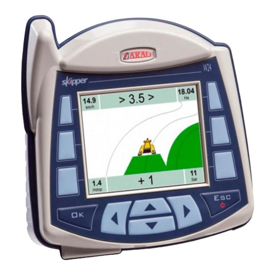
7.2 Display guidance Page day disPLay mode night disPLay mode Following page Fig. 95 Fig. 94 g R2 data: spraying job data, customisable by user* a Graphical chart of deviation b. (par. 6.5.4 User preferences - Graphic settings). Every led corresponds to 50 cm. h Sprayed area b Deviation: distance between tractor position and the track to be followed. -
Page 33: Spraying Boom
As far as vehicle moves on, signal will be triggered for every overlapping section. - When overlapping goes back to allowed limits, Skipper LT prompts you to OPEN affected sections (Fig. 100). Open section valve and inform Skipper LT about its opening using the relevant function key (par. 8.1). -
Page 34: Spraying A Field
• While driving field border you will mark two points A and B (as described under par. 8.3.1 - function This step is essential to allow Skipper LT to guide you, during the job, along tracks parallel to the reference one, obtained by marking points A and B. -
Page 35: Work Functions
Par. function function Mark AB Open (LEFT) Store two field points A and B, that Skipper LT will use to 8.1.1 8.3.1 Indicates opening of first closed section valve, create a line to be used as a reference track for spraying job starting from boom left-hand side underway. -
Page 36: Functions List: Page 1 - Section Valves Commands
WORK FUNCTIONS - PAGE 1 8.1 Functions List: PAGE 1 - SECTION VALVES COMMANDS IMPORTANT: Activated function indicates section status but does not make any check on them: valves shall be worked using other devices, referring to the relevant instructions manual. Indicating what happens on the field, Skipper LT could give guidance indications and gather all work data. Using the function keys on PAGE 1 it is possible to indicate "sequential" opening and closing of section valves, from right to left and vice versa, according to the depressed function key. State of spraying boom sections will be displayed (par. 7.3). 8.1.1 Open Press a few times to indicate valve opening, one at a time, from right to left, starting from the first closed section valve (Fig. -
Page 37: Close (Left)
WORK FUNCTIONS - PAGE 1 8.1.3 Press a few times to indicate valve closing, one at a time, from left to right, starting from the first opened section valve Close (Fig. 108). (LEFT) Fig. 108 8.1.4 Press a few times to indicate valve closing, one at a time, from right to left, starting from the first opened section valve Close (Fig. -
Page 38: Functions List
WORK FUNCTIONS - PAGE 2 8.2 Functions List: PAGE 2 Store job breaking point "Pause" on field, represented by a flag at the point where it is stored 8.2.1 Flag can be seen on guidance page (Fig. 111) and on field full zoom page (Fig. 112). Pause "Pause"... -
Page 39: F2 Mode
WORK FUNCTIONS - PAGE 2 8.2.2 Straight parallel Curved parallel Select guidance mode between Mode Press 2 Selection page is displayed: press to scroll across items. 3 Confirm selection. Fig. 113 Fig. 114 straight ParaLLeL curVed ParaLLeL Fig. 115 Fig. 116 Track on display will be used as driving reference and are perfectly straight and Displayed tracks will be used as driving reference and are parallel with each other, they feature no straight but ONLY with trajectories with not too sharp curves. -
Page 40: F3 Return
- Once you reach the flag position, distance value gets to "zero" (Fig. 119): press to quit this procedure. Skipper LT recalls spraying job guidance information and flag is deleted. Skipper LT recalls spraying job guidance information but flag remains memorised. -
Page 41: F4 Align
WORK FUNCTIONS - PAGE 2 8.2.4 Shift the closest reference track and realign it to machine position Align Press if you need to realign, maintaining the same direction (such as with maize, sugar cane). - Set to the position you would like to set as new reference track and press - The "old"... -
Page 42: F5 Area
WORK FUNCTIONS - PAGE 2 8.2.5 Activate the procedure to calculate the field area, while driving on borders Area Press start the procedure and calculate the area (functions list is no longer displayed). Select field border Message is displayed to set machine side to be used as field outer edge. Left Right Press... -
Page 43: Functions List
WORK FUNCTIONS - PAGE 3 8.3 Functions List: PAGE 3 Stores two points A and B on field; they are used by Skipper LT to create a line to be used as reference track 8.3.1 (t0, Fig. 129) for spraying job underway. Mark AB... -
Page 44: F2 Day / Night
WORK FUNCTIONS - PAGE 3 8.3.2 Toggle from day display guidance mode to night one and vice versa (Figures 130 - 131) Day / Default display mode is Day. Following are the two possible instances: Night day disPLay mode night disPLay mode 1a Night display mode is active. -
Page 45: Functions List
* "machine": includes all settings you set up during Skipper LT programming (chapt. 6.5), concerning tractor you will use for the job. For instance, you could use Skipper LT with many machines so to obtain the correct information you shall recall the features of the machine in use. -
Page 46: F2 2D-3D
WORK FUNCTIONS - PAGE 4 Toggle from 2D display guidance mode to 3D one and vice versa (Figures 137 - 138) 8.4.2 2D-3D Default display mode is 2D. Following are the two possible instances: 3d disPLay 2d disPLay 1a 2D display mode is active. 1b 3D display mode is active. -
Page 47: F3 Job Resume
* "machine": includes all settings you set up during Skipper LT programming (chapt. 6.5), concerning tractor you will use for the job. For instance, you could use Skipper LT with many machines so to obtain the correct information you shall recall the features of the machine in use. -
Page 48: F4 Menu
WORK FUNCTIONS - PAGE 4 8.4.4 Displays the menu page for programming Skipper LT (Fig. 145) Menu Press display programming menu. Refer to chapt. 6 to correctly program all menu items. Fig. 145... -
Page 49: F5 Erase
WORK FUNCTIONS - PAGE 4 8.4.5 Delete completed job data. Erase Erase job's information? Press to delete data. Confirmation prompt is displayed (Fig. 146). 2 Press Fig. 146 references about guidance Page Sprayed areas are deleted and job data is reset. Reference tracks are maintained in the memory (par. -
Page 50: Maintenance / Diagnostics / Repairs
Power failure during switch-off: DATA FROM LAST JOB Unable to load last job! Skipper LT has not completed storage of job underway. CAN NOT BE RECOVERED Low memory available! Available internal memory is insufficient to Run the procedure to delete files from Delete jobs to free memory start a new job or save data. -
Page 51: Technical Data
TECHNICAL DATA technicaL data descriPtion skipper Lt Display LCD 4", 65000 colors, 350 cd/m Power supply 9 - 15 Vdc 0 °C ÷ 45 °C Working temperature +32 °F ÷ +113 °F -20 °C ÷ 60 °C Storage temperature -4 °F ÷ +140 °F... -
Page 52: End-Of-Life Disposal
Dispose of the system in compliance with the established legislation in the country of use. guarantee terms 1. ARAG s.r.l. guarantees this apparatus for a period of 360 day (1 year) from the date of sale to the client user (date of the goods delivery note). - Page 53 Notes...
- Page 54 Notes...
- Page 55 Via Palladio, 5/A 42048 Rubiera (RE) - Italy P.IVA 01801480359 Dichiara che il prodotto descrizione: Navigatore satellitare modello: Skipper LT LT serie: 467020 risponde ai requisiti di conformità contemplati nelle seguenti Direttive Europee: 2004/108/CE (Compatibilità Elettromagnetica) Riferimenti alle Norme Applicate: UN EN ISO 14982 : 2001 (Macchine agricole e forestali - Compatibilità...
- Page 56 Only use genuine ARAG accessories or spare parts to make sure manufacturer guaranteed safety conditions are maintained in time. Always refer to ARAG spare parts catalogue. 42048 RUBIERA (Reggio Emilia) - ITALY via Palladio, 5/A Tel. 0522 622011 Fax 0522 628944 http://www.aragnet.com...
Need help?
Do you have a question about the Skipper LT and is the answer not in the manual?
Questions and answers