Advertisement
Quick Links
Download this manual
See also:
Operating Manual
Advertisement

Related Manuals for Siemens FT2080


Summary of Contents for Siemens FT2080
- Page 1 FT2080 Fire terminal (Touch) Mounting Installation Building Technologies A6V10462660_en--_b 2016-04-08 Control Products and Systems...
- Page 2 Issued by: Siemens Switzerland Ltd. Building Technologies Division International Headquarters Gubelstrasse 22 CH-6301 Zug Tel. +41 41 724-2424 www.siemens.com/buildingtechnologies Edition: 2016-04-08 Document ID: A6V10462660_en--_b © Siemens Switzerland Ltd, 2015 2 | 24 Building Technologies A6V10462660_en--_b Fire Safety 2016-04-08...
-
Page 3: Table Of Contents
Table of contents Setup of fire terminal (Touch) FT2080 ............. 5 Installation in 19" pedestal housing of the FC2080 ........7 Installation in housing (standard) ............10 Installation in rear panel (FT2080) FHA2039 .......... 11 Installation in desktop housing (FT2080) FHA2040 ......... 16 Technical data.................. - Page 4 4 | 24 Building Technologies A6V10462660_en--_b Fire Safety 2016-04-08...
-
Page 5: Setup Of Fire Terminal (Touch) Ft2080
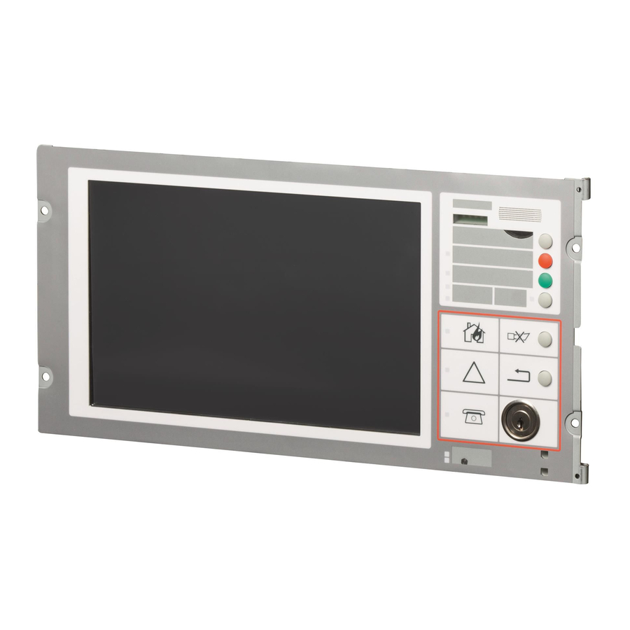
Setup of fire terminal (Touch) FT2080 1 Setup of fire terminal (Touch) FT2080 Figure 1: Rear panel fire terminal (Touch) FT2080 Support plate Front indicator (Touch) FTO2010 PMI & mainboard FCM2027 4x mounting holes in the operating unit Shield plate above carrier (CPU) - Page 6 Setup of fire terminal (Touch) FT2080 Arrangement of components Figure 2: Components on the fire terminal (Touch) FT2080, without cover cap Front indicator (Touch) FTO2010 Main network module (SAFEDLINK) on X13, optional License key, optional Slot 1 [SER_OPT1] for the first serial module at X14, optional...
-
Page 7: Installation In 19" Pedestal Housing Of The Fc2080
Installation in 19" pedestal housing of the FC2080 2 Installation in 19" pedestal housing of the FC2080 The installation instructions described below apply to all operating units. Before an operating terminal is installed, the following components must first be mounted on the operating unit. ●... - Page 8 Installation in 19" pedestal housing of the FC2080 2x fixing screw PMI & mainboard FCM2027 Adapter for power supply (including ribbon cable) Connector strip X3 peripheral data bus connection 1. Plug the network module (SAFEDLINK) (4) into connector X13 (3) of the operating unit (1).
- Page 9 Ribbon cable for FC2080 system supply to card cage (CPU) X30 FCnet connection to card cage (CPU) X11/X12 X3 connection to network module (SAFEDLINK) to PMI & mainboard FCM2027 Inside of door (section view) Fire terminal (Touch) FT2080 Adapter for flat cable of the supply FCnet FCnet FC2080...
-
Page 10: Installation In Housing (Standard)
Rear panel (standard) Fire terminal board FTI2001 Wiring FCnet/SAFEDLINK Network module (SAFEDLINK) FN2001 Fire terminal (Touch) FT2080 X3 Ribbon cable connection from the fire terminal (Touch) to the fire terminal board X1 Supply input for fire terminal board You will find detailed information on wiring the 'fire terminal board FTI2001' and the 'network module (SAFEDLINK) FN2001' in document Product Data 008837. -
Page 11: Installation In Rear Panel (Ft2080) Fha2039
Installation in rear panel (FT2080) FHA2039 4 Installation in rear panel (FT2080) FHA2039 The rear panel (FT2080) can be used for installation in a desk or installation in a third-party housing. Installing the rear panel (FT2080) in a third-party housing guarantees the required EMC protection. - Page 12 Installation in rear panel (FT2080) FHA2039 Installing fire terminal board FTI2001 Figure 9: Installing the fire terminal board in the rear cover (FT2080) Rear panel (FT2080) FHA2039 Fire terminal board FTI2001 4x fixing screws 4x mounting holes Threaded press-in sleeves in rear cover (FT2080) 1.
- Page 13 When installing in a desktop that is thicker than 33 mm, the cables must be routed through the rectangular openings of the rear panel (FT2080), and not through the round cable breakthroughs. Figure 10: Wiring view of the fire terminal (Touch) in the rear cover (FT2080) Fire terminal (Touch) FT2080 Network module (FCnet/SAFEDLINK) FN2001...
- Page 14 Fire terminal (Touch) FT2080 4x fixing screws 4x mounting holes in the fire terminal (Touch) Cable lead-through in the rear panel 4x threaded holes in the rear cover (FT2080) Lateral cable lead-throughs Rear panel (FT2080) FHA2039 Cut-out in the desktop Desktop 1.
- Page 15 Installation in rear panel (FT2080) FHA2039 Installing the rear cover (FT2080) in a desktop Figure 12: Installing the rear cover (FT2080) in a desktop Rear panel (FT2080) FHA2039 Mounted fire terminal (Touch) FT2080 4x fixing screws Mounting holes in the flanges of the rear panel (FT2080)
-
Page 16: Installation In Desktop Housing (Ft2080) Fha2040
Installation in desktop housing (FT2080) FHA2040 5 Installation in desktop housing (FT2080) FHA2040 Figure 13: View of desktop housing (FT2080) Top of desktop housing Tilting bracket for top of housing Base of desktop housing M4x10 pan head screw (scope of delivery) - Page 17 Installation in desktop housing (FT2080) FHA2040 1. Remove the top of housing (1) by pushing the two tilting brackets (2) on the left and right inwards until you can lift off the top of housing. 2. Connect the ground connection as shown with clamping bracket (5) and M4 pan head screw (4).
- Page 18 Installation in desktop housing (FT2080) FHA2040 Installing fire terminal (Touch) FT2080 Figure 15: Mounting in top of housing Tilting brackets on left and right for fixing the top of the housing 2x fixing screws for tilting brackets and fire terminal...
- Page 19 Installation in desktop housing (FT2080) FHA2040 Assembly of desktop housing (FT2080) Figure 16: Assembly of desktop housing Fire terminal (Touch) FT2080 Top of desktop housing (FT2080) FHA2040 Tilting brackets on left and right for fixing the top of the housing...
- Page 20 Installation in desktop housing (FT2080) FHA2040 Figure 17: Securing the top of the desktop housing Securing cap (scope of delivery) Opening for fixing screw Top of the desktop housing (Touch) Fixing screw with securing device 1. To close the housing, tilt the top of the housing (3) onto the housing and secure the top to the housing using both screws (4).
- Page 21 Installation in desktop housing (FT2080) FHA2040 Fire terminal wiring Figure 18: Wiring view of the fire terminal in the desktop housing Fire terminal (Touch) FT2080 Network module (FCnet/SAFEDLINK) FN2001 Fire terminal board FTI2001 Prefabricated cable for supply connection to X7 fire terminal board...
-
Page 22: Technical Data
Technical data: see doc. 008836 FT2080 - Control and Indicating Terminal for use in fire detection and fire alarm systems installed in buildings. 2014/30/EU (EMC): EN 50130-4 / EN 61000-6-3 ; 2014/35/EU (LVD): EN 60950-1 ; 2011/65/EU (RoHS): EN 50581 The declared conformity can be seen in the EU Declaration of Conformity (DoC), which is obtainable via the Customer Support Center: Tel. - Page 23 Technical data 23 | 24 A6V10462660_en--_b Building Technologies Fire Safety 2016-04-08...
- Page 24 Issued by © Siemens Switzerland Ltd, 2015 Siemens Switzerland Ltd Technical specifications and availability subject to change without notice. Building Technologies Division International Headquarters Gubelstrasse 22 CH-6301 Zug +41 41-724 24 24 www.siemens.com/buildingtechnologies Document ID: A6V10462660_en--_b FS20 A5Q00068323 Edition: 2016-04-08...
Need help?
Do you have a question about the FT2080 and is the answer not in the manual?
Questions and answers