Table of Contents
Advertisement
®
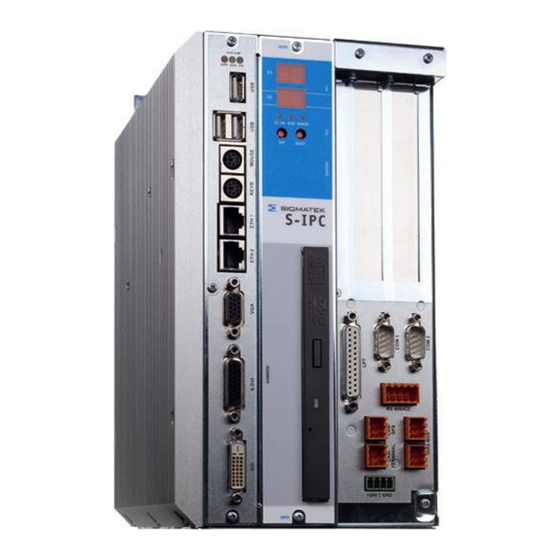
S-IPC INTEL
ATOM DUAL CORE
®
S-IPC Intel
Atom Dual Core
S-IPC with Heat Sink
S-IPC with Heat Sink and Fan Unit
®
The S-IPC is a C-DIAS industrial PC with an Intel
Atom Dual Core processor. The Speed-
®
Step function of the Intel
Atom Dual Core processor enables passive cooling with a heat
sink. For high ambient temperatures, a fan unit is recommended (image right). A 7-segment
display and 6 status LEDs provide information on the actual module status. 2 CompactFlash
cards can be used as program or date memory. An exchangeable drive unit can equipped
with 2 additional IDE devices (hard drive, CD ROM). Among other things, the S-IPC also
has an S-DVI interface for a display terminal and a USB 2.0 interface. 2 PCI expansion
cards can also be inserted.
Compatibility
The S-IPC is completely compatible with the PC and operates with standard PC BIOS; no
Sigmatek-specific BIOS settings are therefore needed. Windows XP is provided as the
operating system.
21.02.2014
Page 1
Advertisement
Table of Contents

Related Manuals for SIGMATEK S-IPC

Summary of Contents for SIGMATEK S-IPC
- Page 1 An exchangeable drive unit can equipped with 2 additional IDE devices (hard drive, CD ROM). Among other things, the S-IPC also has an S-DVI interface for a display terminal and a USB 2.0 interface. 2 PCI expansion cards can also be inserted.
-
Page 2: Table Of Contents
5. DIAS bus connection to C-DIAS modules......... 34 6. Connecting DIAS Modules ..............35 7. CAN Bus Termination................ 36 8. USB Interface Connections ............... 37 9. RS485 Bus Termination ..............38 Pictures of the S-IPC ................39 Page 2 21.02.2014... -
Page 3: Technical Data
® S-IPC INTEL ATOM DUAL CORE Technical Data Performance data ® Processor Intel Atom D510 (1.66 GHz, Dual Core) / 1 Mbytes L2 Cache Internal program memory (CompactFlash) 2x CompactFlash Type I or II Drive unit 1 x 40 Gbytes hard drive... - Page 4 Available current for PCI (+12 V) Maximum 1.0 A Available current for PCI (-12 V) Maximum 0.5 A Available current for PCI (+5 V) Maximum 1.5 A Miscellaneous Article connections S-IPC complete Article DDR-Ram HDD Gbytes CD-Rom / Fan / heat devices:...
- Page 5 ® S-IPC INTEL ATOM DUAL CORE Environmental conditions Storage temperature -20 – +65 °C Operating temperature S-IPC S-IPC without using the PCI slots using the PCI slots Cooling with the fan unit +5 – +55 °C +5 – +50 °C Cooling with a heat sink +5 –...
-
Page 6: Postcodes
S-IPC does not boot Lorsque le S-IPC est sous tension, les BIOS power-on self-test codes sont affichés à l'é- cran. Il est important de noter ces codes afin de rendre le dépannage plus facile si le S-IPC ne démarre pas. -
Page 7: Mechanical Dimensions (With Fan And Heat Sink)
® S-IPC INTEL ATOM DUAL CORE Mechanical Dimensions (with fan and heat sink) 21.02.2014 Page 7... -
Page 8: Mechanical Dimensions (With Heat Sink)
® S-IPC INTEL ATOM DUAL CORE Mechanical Dimensions (with heat sink) Page 8 21.02.2014... -
Page 9: Mechanical Dimensions (Mounts)
® S-IPC INTEL ATOM DUAL CORE Mechanical Dimensions (mounts) Earth terminal 21.02.2014 Page 9... -
Page 10: Connector Layout
® S-IPC INTEL ATOM DUAL CORE Connector Layout Page 10 21.02.2014... -
Page 11: Front Connectors
® S-IPC INTEL ATOM DUAL CORE Front connectors X1 – 3: USB 1 – 3 (Type A) Function +5 V X4: PS2 mouse Function MOUSE DATA 2, 6 Not used +5 V MOUSE CLOCK X5: PS2 keyboard Function KEYBOARD DATA... - Page 12 ® S-IPC INTEL ATOM DUAL CORE X6, 7: Ethernet 1, 2 (8-pin RJ45) Function TD– Not used Not used RD– Not used Not used X8: VGA output (15-pin HD-DSUB) Function Green Blue Nicht belegt Red GND Green GND Blue GND...
- Page 13 ® S-IPC INTEL ATOM DUAL CORE X9: S-DVI (26-pin HD-DSUB) Function Function DVI1+ DVI1- DVI2+ DVI2- DVI3+ DVI3- +24 V DVIC+ +24 V DVIC- USB Ext. In+ Reserved USB Ext. In- USB Ext. Out+ USB Ext. Out- CAN A CAN B X9 cannot be connected while voltage is applied! The +24 V supply must be turned off.
- Page 14 VCC-FAN Monitor 1 Monitor 2 If the fan unit available from Sigmatek (article number: 12-410-011) is not used, a conven- tional +24 V fan with a maximum current consumption of 250 mA can be connected! X12: LPT 1 (25-pin DSUB)
- Page 15 ® S-IPC INTEL ATOM DUAL CORE X15: COM 2 – RS485/422 (10-pin Weidmüller plug) RS422 * RS485 RS422 TxD+ RS485 A RS422 TxD- RS485 B RS422 RxD+ RS485 A RS422 RxD- RS485 B +5 V +5 V RS422 TxD+ RS485 A...
- Page 16 ® S-IPC INTEL ATOM DUAL CORE X18, 19: DIAS bus (6-pin Weidmüller plug) Function MBUS+ MBUS- SBUS+ SBUS- Not used X20: Power supply (4-pin Phoenix RM3.5) Function +24 V +24 V Applicable connectors Type A USB: 8-pin RJ45 Ethernet: 15-pin HD-DSUB plug...
-
Page 17: Bottom Connectors
® S-IPC INTEL ATOM DUAL CORE Bottom Connectors X21: C-DIAS Bus Connector The S-IPC can be mounted on the left of a CMB. 21.02.2014 Page 17... -
Page 18: Status Displays
® S-IPC INTEL ATOM DUAL CORE Status Displays LED 1 Green DC OK Lights when the supply voltage is correct. LED 2 Green Lights when the program is running LED 3 ERROR Lights when a program error occurs. Button 1 Set/display Ethernet, CAN address, power on. - Page 19 ® S-IPC INTEL ATOM DUAL CORE LED 1 1.00 s on/off: EEProm error 0.50 s on/off: temperature sensor – over temperature 0.25 s off/on: fan error 0.10 s off/on: battery – over temperature LED 2 Yellow Lights when the hard drive is accessed.
-
Page 20: Sigmatek Components
® S-IPC INTEL ATOM DUAL CORE Sigmatek Components • 7-segment display for CPU status • Reset button • Set button • DC OK LED • Error LED • Run LED • Timer - 1 µs precision with Interrupt capability •... -
Page 21: S-Ipc Status
® S-IPC INTEL ATOM DUAL CORE S-IPC Status When installing the Sigmatek driver, a "Sigmatek" program group is created that contains the "SipcInfo" program. The program and driver version, as well as several hardware parameters are dis- played: Restart counter... - Page 22 ATOM DUAL CORE With a cooling defect (fan defective, ambient temperature too high), as well as a critical error, an error message is generated by the S-IPC: T Cancel error messages: The alarm can be delayed for any amount of time by entering the desired value in the "Suppress alarms for the next [] seconds"...
- Page 23 ® S-IPC INTEL ATOM DUAL CORE With the help from the "net stop sipclaunch" command, the alarm mes- sages are deactivated until the next restart ("Start" – "execute" or the se- lect input requirement). The service is thereby ended. With „net start sipclaunch“ the service and therewith the alarm messages...
-
Page 24: Exchanging The Compactflash Card
® S-IPC INTEL ATOM DUAL CORE Exchanging the CompactFlash Card exchange CompactFlash cards, the 2 mounting screws for the 7-segmatek display / drive unit must be removed. The cover can then be removed by pulling it straight forward. Locking Screws The master CompactFlash and the slave can now be exchanged. -
Page 25: Exchanging The Battery
® S-IPC INTEL ATOM DUAL CORE Une carte CompactFlash ne peut être échangée tandis que la tension est présente! Vu que la carte Compact Flash est utilisée comme un module d'IDE, on ne peut pas l'é- changer pendant que le système est en marche. -
Page 26: Buffer Battery
ATTENTION: La pile ne doit être changée que si le S-IPC est éteint! Après avoir débranché l'alimentation +24 V, la pile est tamponnée pendant 5 minutes (via ELKO). La pile doit être remplacée pendant ce laps de temps sinon les données seront perdues. -
Page 27: Exchanging The Fan
Should one of the two fans fail, the software shows the status (+ status LED). In this case, the S-IPC can continue to operate with only one fan until the defective fan unit is replace. Under some conditions, the maximum ambient temperature cannot be reached by the time the fan unit is replace. -
Page 28: Mounting Pci Cards
® S-IPC INTEL ATOM DUAL CORE Mounting PCI Cards To open the side panel, 3 mounting screws must be removed. Afterwards, the side panel can be lifted and removed upward. Page 28 21.02.2014... - Page 29 ® S-IPC INTEL ATOM DUAL CORE When remounting the side panel, ensure that the locking mechanism engages cor- rectly. To install the PCI card, the slot bracket must first be removed (1x M3 screw). The mounting screws are used to secure the PCI cards.
-
Page 30: Exchanging The Drive Unit
® S-IPC INTEL ATOM DUAL CORE Exchanging the Drive unit The two mounting screws on the 7- segment display/drive unit and the cover must first be removed. Locking Screws The drive unit can then be removed from the front using the grip. -
Page 31: Cooling
® S-IPC INTEL ATOM DUAL CORE Le lecteur DVD ne peut être modifié que si le S-IPC est éteint (alimentation +24 V déconnecté)! Cooling The S-IPCs power loss can reach up to 100 Watts. Most of the generated heat is removed by the built in fan or the heat sink. -
Page 32: Wiring Guidelines
Wiring Guidelines 1. Earth Connection The S-IPC must be connected to earth through the mounting on control cabinet or over the earth terminal provided. It is important to create a low-ohm earth connection, only then can error-free operation be guaranteed. The earth connection should have the maximum cross section and the largest electrical surface possible. -
Page 33: Shielding
USB keyboards and mouse; these devices are disrupted by ESD and in some instances, no longer function. Before any device is connected to or disconnected from the S-IPC, the potential with ground should be equalized (by touching the control cabinet or earth terminal). Electrostatic loads (through clothing and shoes) can thereby be dissipated. -
Page 34: Dias Bus Termination
If the S-IPC is one to the end modules, the termination can be made with a 100-Ohm resis- tor between MBUS+ and MBUS as well as SBUS+ und SBUS-. If this is the case, the 2 DIAS bus connector is for the remains available. -
Page 35: Connecting Dias Modules
012 /013). 6.1 Connection over a DIC 121 The DIAS bus connection between the S-IPC and DIC 121 is a point-to-point con- nection and must therefore be terminated on both sides. The DIC 121 has an inte- grated bus termination Wiring the S-IPC: o X18: Install bus termination (2x 100 Ω) -
Page 36: Can Bus Termination
ATOM DUAL CORE 6.2 Connection over a DKO 011or DKO 013: If both DIAS bus connections to the S-IPC are needed, a DKO 011 or DKO 013 can be used in combination with a DPS 001 power supply module. Wiring the DIAS modules with a DPS 001:... -
Page 37: Usb Interface Connections
ATOM DUAL CORE 8. USB Interface Connections The S-IPC has a USB interface connection that can be used in LASAL to connect various USB devices (keyboard, mouse, storage media, Hubs …). Several USB devices, which are fully functional in LASAL, can be connected using a hub. -
Page 38: Rs485 Bus Termination
® S-IPC INTEL ATOM DUAL CORE 9. RS485 Bus Termination The RS485 wired as a continuous line and connected to each bus end to avoid reflections. Here, there are 2 termination types: Bus termination with quiescent level definition: Both 330 – 390 Ω resistors ensure a defined bus status when all participants are passive (receive). -
Page 39: Pictures Of The S-Ipc
The ETX board can be accessed by removing the heat sink. This may be necessary to exchange the memory (DDR Ram). When assembling the S-IPC, caution must be taken to ensure that no contamination gets between the GAP pads (here: pink) and the heat sink! On peut accéder à... - Page 40 ® S-IPC INTEL ATOM DUAL CORE View without ETX board Page 40 21.02.2014...
- Page 41 S-IPC with heat sink and fan At extreme ambient temperatures (high ambient temperature, continuous high processor load), a fan unit should be mounted onto an S-IPC with a heat sink to extend the life of the CD Rom/DVD and hard drive! Dans des conditions environnementales extrêmes (températures élevées, charge élevée du...
- Page 42 ® S-IPC INTEL ATOM DUAL CORE Page 42 21.02.2014...
Need help?
Do you have a question about the S-IPC and is the answer not in the manual?
Questions and answers