Advertisement
ST710-KHJV.03
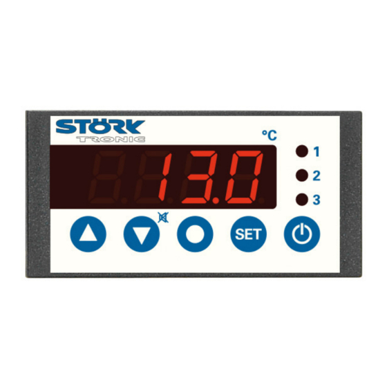
Temperature controller
Order number 900210.008
Wiring diagram
Product description
The switching outputs of the thermal controller can be programmed as
-two-point controller with alarm
-three-point controller with alarm contact
-two-stage controller with alarm contact
-three-stage controller.
Beside the standby key there is a second key to set functions, which can be variously parametered.
Sensor: PTC
Range: -50...150 C
Front size: 84mm x 42mm
Panel cut-out: 67,5mm x 31,5mm
Tightness: front IP65
Connector: plug and socket
Power supply: 12-24V /16-36V=
Advertisement
Table of Contents

Related Manuals for STORK TRONIC ST710-KHJV.03


Summary of Contents for STORK TRONIC ST710-KHJV.03
-
Page 1: Wiring Diagram
ST710-KHJV.03 Temperature controller Order number 900210.008 Wiring diagram Product description The switching outputs of the thermal controller can be programmed as -two-point controller with alarm -three-point controller with alarm contact -two-stage controller with alarm contact -three-stage controller. Beside the standby key there is a second key to set functions, which can be variously parametered. - Page 3 SOFTWARE .03 Adjustment options Key 1: UP Pressing this key you can increase the parameter or parameter value or scroll the parameter list. Key 2: DOWN Pressing this key you can decrease the parameter or parameter value or scroll the parameter list.
- Page 4 Second control level (P parameters): Setting of control parameters Simultaneously pressing the UP and DOWN key for at least 4 seconds opens a parameter list containing control parameters. With the UP and DOWN keys the list can be scrolled in both directions. Pressing the SET key will give you the value of the respective parameter.
- Page 5 Parameter description: P0: Actual value The here indicated temperature presents the actual measured value. If the control setpoint is indicated by the help of parameter A32, the actual value can only be seen with this parameter. P1: Setpoint / DeltaW for control circuit 2 Adjusting the setpoint of control circuit 2.
- Page 6 P30: Lower alarm value P31: Upper alarm value The exit alarm is a boundary alarm or a range alarm with one-sided hysteresis (see parameter P32). Both at the boundary alarm and the range alarm, limit values can be relative, i.e. going along with the setpoint S1/S1’, or absolute, i.e.
- Page 7 Third control level, (A parameters): Setting of control parameters Access to the third control level is granted when selecting the last P-parameter on the second control level. Continue to press the UP key for approximately 10 seconds until “PA” appears. Continue to press the UP key and additionally press the DOWN key for about 4 seconds and the first A-parameter of the third control level is indicated.
- Page 8 Para- Function description Adjustment range Standard Custom meter setting setting Special function at boundary or 0: no special function range alarm 1: flashing display 2: buzzer 3: flashing display and buzzer 4: like 3, buzzer can be cancelled 5: like 4, cancelled buzzer restarts after 10 min.
- Page 9 Para- Function description Adjustment range Standard Custom meter setting setting Temperature scale and display 0: Fahrenheit (“AUS”) when in Standby-Mode 1: Celsius (“AUS”) 2: Fahrenheit (“OFF”) 3: Celsius (“OFF”) Function input E1 0: no function 1: controller On/Off (Standby) 2: setpoint S1‘ activated 3: like 2, status indicated by LED3 Function key 5 0: no function...
- Page 10 Parameter description: The following values can change the equipment characteristics and are therefore to be set with utmost care. A1: Switch mode contact K1 A2: Switch mode contact K2 The switch mode for the relays, i.e. cooling or heating function, can be programmed independently at works.
- Page 11 A32: Setpoint display A32=0 indicates the actual value, A32=1 statically indicates the setpoint S1 or S1’ in the display. Therefore, the current actual value can only be indicated with parameter P0. A33: Adjustment of setpoint S1‘ (not available on all types of controllers) By closing switching input E1, setpoint S1 can be switched to a setpoint S1’.
- Page 12 A81: Function E1 With this parameter function of the ext. input E1 can be set. With A81=0 the E1 is not evaluated. With A81=1 the controller is switched to the standby mode. With A81=2 or A81=3 setpoint S1 is switched to setpoint S1’ when input E1 is closed. With A81=3 the status of E1 is indicated by LED3 in the display.
- Page 13 Technical data of ST710-KHJV.03 Input Switching input for an external potential-free switch, function see parameter A81 Measuring input Resistance thermometer PTC Measuring range: -50°C...+150°C Measuring accuracy: ±0.5K ± 0.5 % at 25°C, without sensor ±1K ± 0.5 % of scale range (0...+55°C), without sensor...
Need help?
Do you have a question about the ST710-KHJV.03 and is the answer not in the manual?
Questions and answers