Table of Contents
Advertisement
ST48-WHDVM.04
Differential temperature controller
Order number 900304.006
Old Id.Nr.: 141648
Wiring diagram
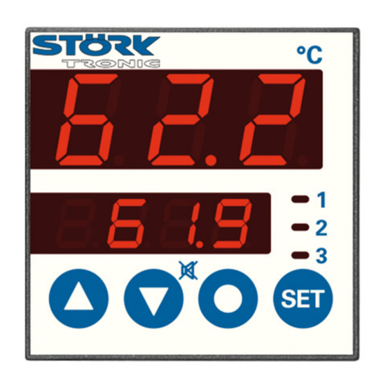
Product description
The PID differential temperature controller with two 3-digit LED seven segment displays, 4 keys
and 3 relays is variably applicable due to its freely programmable general functions. The relay
contact K1 directly affects the main setpoint, formed by reference variable and the given offset
temperature. Contact K2 affects the secondary setpoint which is formed by the main setpoint via
overlap or which alternatively can be freely defined. Contact K3 affects adjustable limit values.
Sensor: Pt100
Range: -99...750 C
Front size: 48mm x 48mm
Panel cut-out: 45.2mm x 45.2mm
Connector: plug and socket
Advertisement
Table of Contents

Related Manuals for STORK TRONIC ST48-WHDVM.04


Summary of Contents for STORK TRONIC ST48-WHDVM.04
-
Page 1: Wiring Diagram
ST48-WHDVM.04 Differential temperature controller Order number 900304.006 Old Id.Nr.: 141648 Wiring diagram Product description The PID differential temperature controller with two 3-digit LED seven segment displays, 4 keys and 3 relays is variably applicable due to its freely programmable general functions. The relay contact K1 directly affects the main setpoint, formed by reference variable and the given offset temperature. - Page 3 SOFTWARE .04 Adjustment options Key UP Pressing this key you can increase the parameter or parameter value or scroll the parameter list. Key DOWN Pressing this key you can decrease the parameter or parameter value or scroll the parameter list. At alarm the buzzer function can be switched off with this key. Function key 1 Different functions are assigned to this key by help of parameters.
- Page 4 Second control level (P parameters): Setting of control parameters Simultaneously pressing the UP and DOWN key for at least 4 seconds opens a parameter list containing control parameters. With the UP and DOWN keys the list can be scrolled in both directions.
- Page 5 Para- Function description Adjustment range Standard Custom meter setting setting Lower limit of the following value -99...999°C 0,0°C for 0 or 10V at analogue output Output voltage for values lower 0: 0V than P46 1: 10V Upper limit of the following value -99...999°C 10,0°C for 0 or 10V at analogue output...
- Page 6 Parameter description: P1: Setpoint / DeltaW for control circuit 2 Adjusting the setpoint of control circuit 2. If A5=1, the setpoints for control circuit 1 and 2 are linked with one another via switching difference DeltaW, which can be adjusted with P1. (operation with DeltaW) The following applies: setpoint thermostat 2 = setpoint control circuit 1 + delta W2.
- Page 7 to rapid wear of relay contacts. For very fast control ways with the respective high switching frequency a voltage output is therefore of advantage. P19: Key-lock The key-lock allows blocking of the control keys. In locked condition parameter adjustments with keys is not possible.
- Page 8 P32 Hysteresis alarm contact The hysteresis can be set symmetrically or one-sided at the adjusted limit values. (see A42). It becomes effective depending on alarm definition. At one-sided setting and boundary alarm the hysteresis is effective above the lower and below the upper limit value. At one-sided setting and range alarm the hysteresis is effective above the upper and below the lower limit value.
- Page 9 Scaling examples of analogue output: Scaling example 1: Scaling example 2: Indication range of the variable for heating Indication range of the variable for heating is and cooling is -10.0 ... +10.0 V +2.0 ... +10.0 V with P43 = 10.0; P44 = 0.0; P45 = -10.0. with P43 = 10.0;...
- Page 10 P46: Lower limit of the following value for 0 or 10V at analogue output If the following value drops below this limit, the output voltage is according to parameter P47. P47: Output voltage for values lower than P46 Output voltage below the limit set with parameter P46. P48: Upper limit of the following value for 0 or 10V at analogue output If the following value goes above this limit, the output voltage is according to parameter P49.
- Page 11 Third control level (A parameters): Setting of control parameters Access to the third control level is granted when selecting the last P-parameter on the second control level. Continue to press the UP key for approximately 10 seconds until “PA” appears. Continue to press the UP key and additionally press the DOWN key for about 4 seconds and the first A-parameter of the third control level is indicated.
- Page 12 Para- Function description Adjustment range Standard Custom meter setting setting Special function at boundary 0: no special function alarm 1: buzzer 2: flashing display 3: flashing display and buzzer 4: like 3, buzzer can be cancelled 5: like 4, cancelled buzzer restarts after 10 min.
- Page 13 Para- Function description Adjustment range Standard Custom meter setting setting Function output K2 0: no connection 1: connection to contact K1 2: connection to contact K2 3: connection to alarm contact 4: connection to ready message Function output K3 0: no connection 1: connection to contact K1 2: connection to contact K2 3: connection to alarm contact...
- Page 14 Parameter description The following values can change the equipment characteristics and are therefore to be set with utmost care. A1: Switch mode contact K1 A2: Switch mode contact K2 The switch mode for the relays, i.e. cooling or heating function, can be programmed independently at works.
- Page 15 A23: Alarm suppression after "Power-On" This parameter allows a switching-on delay of the alarm contact after switching on the mains voltage. This suppression corresponds with the time set here. The suppression is only active when the alarm is activated the first time. The suppression not to the contacts K1 and K2. A30: Function alarm exit The alarm exit evaluates an upper and a lower limit value (see parameters P30 and P31), whereas a selection is possible as to whether the alarm is active if the temperature lies within these two...
- Page 16 of the hysteresis’ value is effective below and half of the value above the switching point. The one- sided hysteresis works downward with heating contact and upward with cooling contact. A60: Sensor type These parameters permit selection of the sensor type, if the needed hardware prerequisites are available.
- Page 17 LON-bus and serial communication General note The control program has some standardized variables of type “SNVT” which permit the communication with external units via LON-bus. There are input and output values. The input values permit settings for the controller, which are directly available for the control process. The output values indicate measuring values and status information of the unit.
- Page 18 Connection to data logger General note The following listed measuring values as well as the inputs and outputs are available for the data logger TRL1 via LON interface. In general the setpoints and parameters all are accessible. Data logger protocol Parameter values (read/write) Adjustable parameters P1,P2,P3,P4,P5,P7,P8,P9,P10,P19,P21,P23,...
- Page 19 Status messages Message Cause Error elimination Sensor error Check sensor (open- or short-circuit at sensor F1) Sensor error Check sensor (open- or short-circuit at sensor F2) _ _ _ Keyboard lock active see Parameter P19 or A19 Flashing display Temperature alarm (see A31) cancel buzzer with DOWN button Data loss at parameter memory If error cannot be eliminated by...
- Page 20 Technical data of ST48-WHDVM.04 Measuring input Sensor following value Sensor leading value Sensor type Resistance thermometer Pt100 Measuring range: -99°C...+750 °C Measuring accuracy at 25°C: +/-0.5K +/-0.5% of measuring range Outputs Relay, normally-open contact, 8(1,5)A 28V, function see parameter U1...
Need help?
Do you have a question about the ST48-WHDVM.04 and is the answer not in the manual?
Questions and answers