Table of Contents
Advertisement
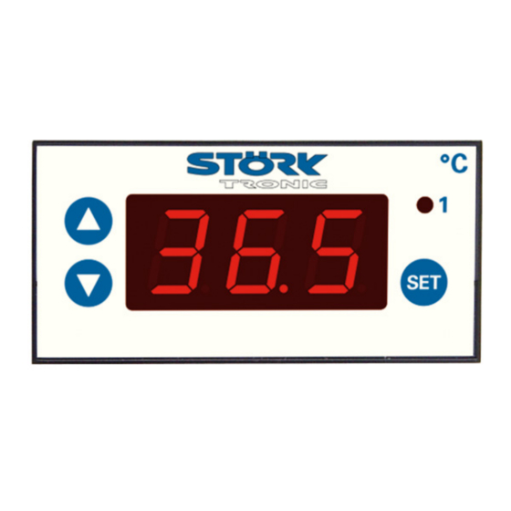
ST70-31.03
Temperature controller
Order number 900380.004
Wiring diagram
Product description
The switching exits of the thermostatic controller can be programmed as
-two-point controller with alarm
-three-point controller
-two-stage controller
-controller with ramp profile.
The setpoint and all parameters of the controller are set on a three-field plastic foil keyboard.
Sensor: Pt100-3 wire
Range: -99...600 C
Front size: 72mm x 36mm
Panel cut-out: 68.5mm x 28.5mm
Connector: screw terminal
Advertisement
Table of Contents

Subscribe to Our Youtube Channel
Related Manuals for STORK TRONIC ST70-31.03


Summary of Contents for STORK TRONIC ST70-31.03
-
Page 1: Wiring Diagram
ST70-31.03 Temperature controller Order number 900380.004 Wiring diagram Product description The switching exits of the thermostatic controller can be programmed as -two-point controller with alarm -three-point controller -two-stage controller -controller with ramp profile. The setpoint and all parameters of the controller are set on a three-field plastic foil keyboard. - Page 3 Software .03 Adjustment options Key UP Pressing this key you can increase the parameter or parameter value or scroll the parameter list. Key DOWN Pressing this key you can decrease the parameter or parameter value or scroll the parameter list. At alarm the buzzer function can be switched off with this key. Key 4: SET While SET key is pressed, the setpoint is indicated.
- Page 4 Second control level (P parameters): Setting of control parameters Simultaneously pressing the UP and DOWN key for at least 4 seconds opens a parameter list containing control parameters. With the UP and DOWN keys the list can be scrolled in both directions. Pressing the SET key will give you the value of the respective parameter.
- Page 5 Parameter description: P1: Setpoint / DeltaW for control circuit 2 Adjusting the setpoint of control circuit 2. If A5=1, the setpoints for control circuit 1 and 2 are linked with one another via switching difference DeltaW, which can be adjusted with P1. (operation with DeltaW) The following applies: setpoint thermostat 2 = setpoint control circuit 1 + delta W2.
- Page 6 Fig. 3: relative values Fig. 4: absolute values The main setpoint S1 and the point of ramp Main setpoint S1 and ramp employment point employment are linked as difference with one are independent from each other another. This difference can take positive or negative values, i.e.
- Page 7 Third control level, (A parameters): Setting of control parameters Access to the third control level is granted when selecting the last P-parameter on the second control level. Continue to press the UP key for approximately 10 seconds until “PA” appears. Continue to press the UP key and additionally press the DOWN key for about 4 seconds and the first A-parameter of the third control level is indicated.
- Page 8 Para- Function description Adjustment range Standard Custom meter setting setting Alarm delay after 0...60 min. 0 min. “Power-on” Hysteresis mode 0: symmetrically contact K1 1: one-sided Hysteresis mode 0: symmetrically contact K2 1: one-sided Minimum action time 0...400 sec. 0.0 sec. contact K1 ”On”...
- Page 9 Parameter description: The following values can change the equipment characteristics and are therefore to be set with utmost care. A1: Switch mode contact K1 A2: Switch mode contact K2 The switch mode for the relays, i.e. cooling or heating function, can be programmed independently at works.
- Page 10 A31: Special function at boundary or range alarm Here can be selected whether, in the case of an alarm, the indication to flash and/or the buzzer is to start. Sensor alarm (display F1L or F1H) is indicated independently thereof by flashing display and the buzzer.
- Page 11 Status messages Message Cause Error elimination _ _ _ Key-lock active Change parameter P19 or A19 Sensor error, Check sensor short-circuit at sensor F1 Sensor error, Check sensor open-circuit at sensor F1 Wrong connection of Pt100 sensor Check connection display flashes Temperature alarm at too high or too low temperature (if activated) see A31 Buzzer...
- Page 12 Technical data of ST70-31.03 Measuring input Resistance thermometer Pt100-3L Measuring range: -99...600°C Measuring accuracy: 0.5 K, without sensor Outputs Relay, change-over contact, 5A 250V (cosϕ=1) Relay, change-over contact, 5A 250V (cosϕ=1) Display 3-digit LED Display, colour red 1 LED for status display Power supply 12...24 V AC (50/60 Hz) or 16...36V DC...
Need help?
Do you have a question about the ST70-31.03 and is the answer not in the manual?
Questions and answers