Advertisement
Quick Links
ST501-LN1KV.04
Differential temperature controller
Order number 900219.015
Old Id.Nr.: 228221
Wiring diagram
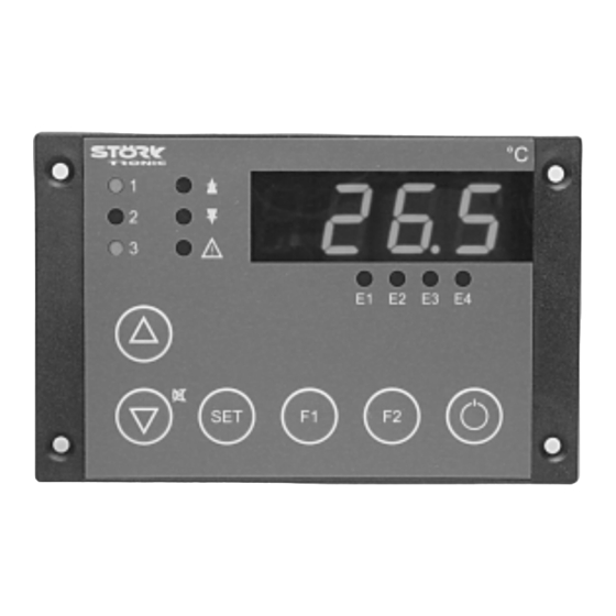
Product description
The differential temperature controller with 3-digit LED seven segment display, 6 keys and 4 relays
is variably applicable due to its freely programmable general functions. Either differential or stan-
dard regulation can be selected via parameters. With four digital inputs a logic evaluates status
messages from a connected refrigerating plant and thus guarantees a defined operational se-
quence under all conditions.
As a special feature of the power board the output relay for the compressor is switched off as soon
as the digital input for the high pressure alarm is opened.
Sensor: PTC
Range: -50...130 C
Front size: 106mm x 68mm
Panel cut-out: 87.5mm x 56.5mm
Connector: screw terminal
Advertisement

Subscribe to Our Youtube Channel
Related Manuals for STORK TRONIC ST501-LN1KV.04


Summary of Contents for STORK TRONIC ST501-LN1KV.04
-
Page 1: Wiring Diagram
ST501-LN1KV.04 Differential temperature controller Order number 900219.015 Old Id.Nr.: 228221 Wiring diagram Product description The differential temperature controller with 3-digit LED seven segment display, 6 keys and 4 relays is variably applicable due to its freely programmable general functions. Either differential or stan- dard regulation can be selected via parameters. - Page 3 Technical data of ST501-LN1KV.04 Inputs extern potential-free switching input for pump failure, closed at failure extern potential-free switching input for high pressure alarm, opened at alarm extern potential-free switching input for low pressure alarm, opened at alarm extern potential-free switching input for ventilator failure, opened at failure...
Need help?
Do you have a question about the ST501-LN1KV.04 and is the answer not in the manual?
Questions and answers