Table of Contents
Advertisement
Advertisement
Table of Contents

Related Manuals for Reely HT-6


Summary of Contents for Reely HT-6
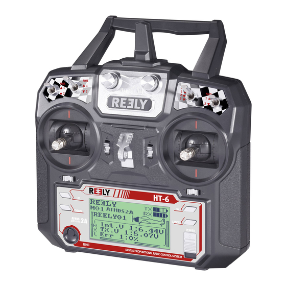
- Page 1 ( Remote Control „HT-6“ 2,4 GHz Item no. 1310037 Version 04/15...
-
Page 2: Table Of Contents
Table of Contents Page Introduction ................................4 Explanation of Symbols ............................4 Intended Use ...............................5 Product Description .............................5 Scope of Delivery ..............................6 Safety Information ..............................6 a) General Information ............................6 b) Operation ...............................7 Notes on Batteries and Rechargeable Batteries ....................8 Charging Rechargeable Batteries ........................8 Transmitter Controls ............................9 10. - Page 3 Page g) Operation as Trainer Transmitter „Trainer Mode“ ..................32 h) Operation as Student Transmitter „Student Mode“ ..................33 i) Control Stick Assignment „Sticks Mode“ ......................34 j) Display Brightness „LCD Brightness“ ......................35 k) Transmitter Software Version „Firmware Ver.“ .....................36 l) Transmitter Software Update „Firmware Update“ ..................37 m) Reset to Factory Settings „Factory Reset“...
-
Page 4: Introduction
Introduction Dear Customer, thank you for purchasing this product. This product complies with the statutory national and European requirements. To maintain this status and to ensure safe operation, you as the user must observe these operating instructions! These operating instructions are part of this product. They contain important notes on commissioning and handling. -
Page 5: Intended Use
Intended Use The 6-channel remote control „HT-6“ is solely designed for private use in the field of model construction and the operating times associated with it. This system is not suitable for industrial use, such as controlling machines or equipment. -
Page 6: Scope Of Delivery
Scope of Delivery • Remote control transmitter • Remote control receiver • Binding plug • Operating instructions Safety Information In case of damage caused by non-compliance with these operating instructions, the warranty/gua- rantee will expire. We do not assume any liability for consequential damage! We do not assume any liability for property damage and personal injury caused by improper use or non-compliance with the safety instructions! In such cases the warranty/guarantee is voided. -
Page 7: B) Operation
b) Operation • If you do not yet have sufficient knowledge on how to deal with remote-controlled models, please contact an expe- rienced model sportsman or a model construction club. • When putting the device into operation, always turn on the transmitter first. Then switch on the receiver in the model. Otherwise, the model might show unpredictable responses! • Before operating the model, check whether the stationary model reacts as expected to the commands of the remote control. • When you operate the model, always make sure that no parts of your body, other people or objects come within the dangerous range of the motors or any other rotating drive parts. • Improper operation can cause serious damage to people and property! Always make sure that the model is in your line of sight and do not operate it at night. • Only operate your model if your ability to respond is unrestricted. Fatigue or the influence of alcohol or medication can lead to wrong responses. -
Page 8: Notes On Batteries And Rechargeable Batteries
Notes on Batteries and Rechargeable Batteries • Keep batteries/rechargeable batteries out of the reach of children. • Do not leave any batteries/rechargeable batteries lying around openly. There is a risk of batteries being swallowed by children or pets. If swallowed, consult a doctor immediately! • Batteries/rechargeable batteries must never be short-circuited, disassembled or thrown into fire. There is a danger of explosion! • Leaking or damaged batteries/rechargeable batteries can cause chemical burns to skin on contact; therefore, use suitable protective gloves. • Do not recharge normal batteries. There is a risk of fire and explosion! Charge only rechargeable batteries intended for this; use suitable chargers. • Always observe correct polarity (positive/+ and negative/-) when inserting the batteries/rechargeable batteries. • If the device is not used for an extended period of time (e.g. storage), remove the inserted batteries/rechargeable batteries from the remote control and the car to avoid damage from leaking batteries/rechargeable batteries. • Recharge the rechargeable batteries about every 3 months. Otherwise, so-called deep discharge may result, ren- dering the rechargeable batteries useless. -
Page 9: Transmitter Controls
Transmitter Controls Front: Figure 1 1 Transmitter aerial 13 Binding button 2 Carry handle with integrated second transmitter aerial 14 „DOWN“ button 3 Rotary encoder „VRB“ 15 „UP“ button 4 Toggle switch „SWC“ 16 Trim button for rudder/tail function (in mode II)* 5 Toggle switch „SWD“... -
Page 10: Setting Up The Transmitter
Rear: 23 Trainer/student socket 24 Battery compartment lid Figure 2 Setting Up the Transmitter In the further course of these instructions, figures in the text always refer to the adjacent figure or the figures within the section. References to other figures are indicated with the corresponding figure number. a) Inserting the Batteries For the power supply of the transmitter you will need 4 alkaline batteries (e.g. Conrad item no. 652507, pack of 4, order 1) of the size AA/mignon. -
Page 11: B) Switching On The Transmitter
b) Switching on the Transmitter After you have inserted four new batteries, check the position of the toggle switches. All switches must be in the front position. The control stick for the elevator/nod and aileron/roll function (see figure 1, item 7) must be in the middle position. The control stick for the rudder/tail and throttle/pitch functions (see figure 1, item 17) must be in the middle position as well or must be pushed into the bottom-most position (motor off). Now switch on the transmitter using the on/off switch (see fig. 1, item 11). First, you will hear three signal sounds in increasing pitch and the operating display with the currently set model appears in the backlit display. - Page 12 If one of the four toggle switches (see figure 1, items 4, 5, 19 and 20) is not in the front position, and if the control stick for the throttle/pitch function is not in the bottom position, warning sounds are emitted at activa- tion and the corresponding note is displayed. In this case, the affected switches and the control stick must be put in the required position.
-
Page 13: C) Modifying The Throttle Function
Modifying the Throttle Function Ex works, your remote control „HT-6“ is configured so that the control lever for the throttle/pitch function is on the left. This is the most common configuration in Europe. If you prefer to have the throttle/pitch function on the right as opposed to the left stick, you have the option of swapping the two stick units with each other. To make the necessary changes, some experience with remote control transmitters is required. Therefore you should consult an experienced model maker or a model construction club if you do not feel capable of undertaking the pro- cedures described in the following. -
Page 14: D) Setting The Control Stick Length
d) Setting the Control Stick Length You can adjust the length of the control sticks, depending on your steering habits. To do so simply hold the bottom part of the grip (1) and turn the upper part (2) up anti-clockwise. You can now set the length of the control stick by turning the bottom part of the grip. -
Page 15: Setting Up The Receiver
Setting up the Receiver a) Receiver Connection On its right hand side, the receiver (see figure 8, item 1) offers the option of connecting up to 6 servos with JR or Futaba plug connectors. The receiver battery or a battery box is connected to a switch cable either on a free slot or at the top-most slot (B/VCC). Figure 8 When connecting servos and speed controllers, always make sure of correct polarity of the plug connectors. The impulse line of the servos (depending on manufacturer yellow, white or orange) must be connected to the left (inner) one of the three adjacent plug-in contacts. -
Page 16: B) Led Display
* Electric models with an electronic flight controller only require a separate rechargeable receiver battery if the flight controller used does not have a BEC circuit. For further information, refer to the technical documents of the controller. Channels 5 and 6 can be assigned differently depending on model. There also is the option of operating two servos via a V-cable at a receiver output. -
Page 17: C) Mounting The Receiver
c) Installing the Receiver Installation of the receiver depends on the model. For this reason, you should always follow the recommendations of the model manufacturer regarding the installation. Regardless of the model, you should always try to install the receiver so that it is protected from dust, dirt, moisture, heat and vibration in the best possible way. Keep enough distance from motors and electronic flight or speed controllers. Metal or carbon parts have a shielding effect and thus may considerably impair reception. -
Page 18: D) Installing The Servos
d) Mounting the Servos The installation of a servo (1) always depends on the particular model used. Detailed information on this can be found in the construction documents of the model. Generally, however, try screwing in the servos in a vibration- dampened manner. -
Page 19: Programming The Remote Control
Programming the Remote Control Your remote control offers a „System setup“ menu for best ad- justment to your model and a „Functions setup“ menu with diffe- rent menu items that have many subordinated settings as well. Depending on the model type (helicopter or plane model) set in the system menu, the function menu setting options will differ. -
Page 20: The System Setting Menu „System Setup
The System Setting Menu „System Setup“ The basic settings of the remote control transmitter are made in the system setup menu first. These settings are not referred to individual models. The specific settings of the individual models are only made afterwards in the function setting menu (see chapter 14). To get to the system settings menu, push the button „OK“ with the transmitter switched on. The operating display in the display switches to the menu display. The selection window around the remote control icon shows that you can call the „System Setup“... -
Page 21: A) Model Memory Selection „Model Select
a) Model Memory Selection „Model Select“ The remote control system has 20 model memories which allow you to save the data for your respective models independently of one another. Therefore, it is required to set the associated model memory in the transmitter before operating a specific model. -
Page 22: B) Model Name Setting „Model Name
b) Model Name Setting „Model Name“ In order to be able to discern between model memories more easily it makes sense to give the memories the name of the corresponding models. The name can consist of a combination of up to 8 letters, numbers or characters. Caution, important! You can always change only the name of the model memory that is active at the moment. -
Page 23: C) Model Type Selection „Type Select
c) Model Type Selection „Type Select“ As there are different functions available for each of the respective model types, such as mixers or switching functions, it is necessary to enter the right model type during programming. You can pick between model planes „Airplane or glider“... -
Page 24: D) Copying Model Memory „Model Copy
d) Copying Model Memory „Model Copy“ For simple programming of the system you have the option of copying data from one model memory to another. This helps to easily transfer basic settings and mixer between similar models and you only need to adjust the settings values to the new model. -
Page 25: E) Deleting Model Memory „Model Reset
e) Deleting Model Memory „Model Reset“ To remove any present and undesired settings before programming a new model, you can delete individual model memories targetedly and thus rest them to factory settings. Deleting model memory: • Switch on the transmitter and call the system setting menu. • Move the cursor arrow to the menu item „Model reset“ with the two buttons „UP“ and „DOWN“. • Briefly push the button „OK“ to activate the menu item. -
Page 26: F) Receiver Programming „Rx Setup
Receiver Programming „RX Setup“ The remote control „HT-6“ offers the option of setting different receiver parameters or display the measured values. The function of the displays and settings depends on the respective receiver used and the connected sensors. Since the enclosed receiver does not support connection of external sensors, these instructions only deal with the settings that are relevant for the enclosed receiver. -
Page 27: Digital Coding „Afhds 2A
The remote control transmitter enables you to control receivers with the digital code „AFHDS 2A“ and „AFHDS“. Ex works, the transmitter is set to the enclosed „AFHDS 2A“-encoded receiver. If you want to operate a REELY receiver with the digital code „AFHDS“, the transmitter must be switched first and then the receiver must be bound to the transmitter. More information on binding of transmitter and receiver can be taken from chapter 16: Binding Function. -
Page 28: Receiver Voltage „Rx Battery
Receiver voltage „RX battery“ Depending on the receiver voltage supply used, this menu can be used to set the voltage values where the remote control visually and acoustically displays threatening deep discharge. To set the receiver voltages, proceed as follows: • Call the „RX Setup“ menu. -
Page 29: Failsafe Setting „Failsafe
Failsafe setting „Failsafe“ The remote control has the option of automatically moving the servos to a specific position at impairment of the reception signal. This way, the drive motor can be switched off, e.g. in an electrical gliding model that is outside of the transmitter range, and circling can be started. -
Page 30: Sensor List „Sensor List
Sensor list „Sensor list“ The sensor list shows the connected sensors. In case of the en- closed receiver, only the receiver voltage „Int.V“, the transmitter voltage „TX.V“ and the error rate of the receiver signal „Err“ is displayed. The larger the distance between the transmitter and the receiver, and the worse the quality of the receiver signal, the higher the percentage of the defectively received data. -
Page 31: Servo Control Frequency „Servos Freq
Servo control frequency „Servos freq“ Analogue servos are supplied with a control impulse 50 times per second by the receiver. Digital servos in contrast can be controlled much more often. This enables them, among others, to develop high adjustment and holding forces and to move to the specified positions extremely fast. The control frequency a servo can bear can be taken from the technical data sheets of the individual servos. -
Page 32: G) Operation As Trainer Transmitter „Trainer Mode
Operation as Teaching Transmitter „Trainer Mode“ For safe and comfortable model flight training, the remote control system offers a plug-in socket for a trainer-student cable (see figure 2, item 23). An optional cable permits connecting a second remote control type „HT-6“ (or alterna- tively „HT-4“) to your transmitter. When using two „HT-6“ transmitters, one of them must be configured as the teaching transmitter and the other as the student transmitter (see following menu item). The flight trainer can use a freely selectable toggle switch to switch between the control stick signals of the trainer and student transmitter. Configuration as trainer transmitter: • Switch on the transmitter and call the system setting menu. • Move the cursor arrow to the menu item „Trainer mode“ with the two buttons „UP“ and „DOWN“. -
Page 33: H) Operation As Student Transmitter „Student Mode
h) Operation as Student Transmitter „Student Mode“ When configuring as a student transmitter, the signals of the control sticks and the control encoder for channels 5 and 6 are sent directly to the teacher/student socket at the rear independently of the set mode and transferred to the teaching transmitter via the connection cable. If the student transmitter mode is not activated, the six control signals are branched off at the teacher/student socket according to the model type set with all programmed settings and mixers. -
Page 34: I) Control Stick Assignment „Sticks Mode
i) Control Stick Assignment „Sticks Mode“ As described previously for the receiver connection, the individual receiver outlets (channels) have specific functions or servos assigned to them. The first four outputs are assigned as follows: CH1 = channel 1 (aileron/roll servo) CH2 = channel 2 (elevator/nod servo) CH3 = channel 3 (throttle servo/flight controller) CH4 = channel 4 (rudder/tail servo) When setting the control stick assignment, you can exactly determine the control stick you want to use to control outputs 1 - 4. -
Page 35: J) Display Brightness „Lcd Brightness
j) Display Brightness „LCD Brightness“ To have a perfectly legible display signals at all times, you can set the brightness value individually. Setting the brightness value: • Switch on the transmitter and call the system setting menu. • Move the cursor arrow to the menu item „LCD brightness“ with the two buttons „UP“ and „DOWN“. • Briefly push the button „OK“ to activate the menu item. The currently set brightness value is displayed with a nume- ric value and a bar chart in the display. -
Page 36: K) Transmitter Software Version „Firmware Ver
k) Transmitter Software Version „Firmware Ver.“ On demand, you can have the version number and the date of the transmitter software displayed. This way, you can recognise at once whether there is a newer software for the transmitter that can be installed (see following menu item). -
Page 37: L) Transmitter Software Update „Firmware Update
l) Transmitter Software Update „Firmware Update“ To transfer a newer version of the transmitter software to the remote control, the transmitter must be connected to a PC or notebook with an USB interface cable. For the data to be transmitted to the remote control, the transmitter must be put in the update mode. -
Page 38: M) Reset To Factory Settings „Factory Reset
m) Reset to Factory Settings „Factory Reset“ With this function you have the option of deleting all the data of all model memories to their factory settings with a single command. Attention! When you call this function, all previously entered model data and settings are deleted! The remote control is returned to the delivery condition and all data must be entered again. -
Page 39: The Function Setting Menu „Functions Setup
The Function Setting Menu „Functions Setup“ The specific settings for the respective models are made in the function setup menu. The menu items available in the function setup menu depends on which model type was selected in the system setup menu. To get to the function settings menu, push the button „OK“ and hold it with the transmitter switched on. -
Page 40: A) Servo Direction Setting „Reverse
V-tail mixer (flight models only) „V tail“ Gyro sensitivity setting (for helicopter models only) „Gyroscope“ Switch assignment „Switches assign“ Throttle switching „Throttle hold“ The menu items listed in the table are not all available in the function menu at the same time. Depending on the previously selected model type (helicopter or wing model), the menu items not needed or unsuitable for the required model are not displayed. -
Page 41: B) Servo End Deflection Setting „End Points
b) Servo End Deflection Setting „End Points“ Using the servo end deflection setting you can precisely define the maximum size of servo travel that is permitted on each side. The servo end deflection function is typically used to protect servos from mechanically hitting an obstacle when deflecting to the full extent. You can set a value from 0 to 120%. The smaller the value, the shorter the servo travel. Always try to select the linkage points on the servo and the rudder sticks so that they reach maximum rudder deflections at the factory preset value of 100%. The linked rods or sticks should not hit anything or be under any mechanical tension. This ensures that this function is only required to make minimal adjustments. -
Page 42: C) Servo Control/Test „Display
c) Servo Control/Test „Display“ In this menu you can graphically display the servo control settings for all 6 channels and simultaneously check the individual control functions with all mixers. Especially with helicopter models you can easily very quickly make mixer errors for swash plate control. -
Page 43: D) Encoder Assignment „Aux. Channels
d) Encoder Assignment „Aux. Channels“ For the encoder assignment, you can set individual encoders for channels 5 and 6 (rotary encoder or toggle switch). If you have any swash plate mixer or variable pitch control activated in the system setting menu, channel 6 is needed for rotor head linkage and therefore cannot be freely assigned. -
Page 44: E) Basic Trim „Subtrim
e) Basic Trim „Subtrim“ As previously mentioned when installing the servo, always mount the servo stick at a 90° angle to the linkage rods (see fig. 13). The trim displays at the transmitter (see fig. 4, items 5 - 8) should be in the centre position. Only then will you be able to perform fine trimming in both directions using the trim buttons during flight (see fig. 1, item 6, 8, 16 and 18). However, the cog teeth on servo levers are often so large that the exact 90° angle cannot be set (see figure 13). This is why the basic trim helps to set the correct centre position of the servo arm without the need to adjust the trim buttons. -
Page 45: F) Dual Rate/Exponential Setting „Dual Rate/Exp
f) Dual Rate/Exponential Setting „Dual Rate/Exp.“ The dual rate function: The dual rate function allows you to reduce the servo deflections of channels 1, 2 and 4 by operating the flight condi- tion switch. You can do this to simply and easily reduce the reaction sensitivity of a model which reacts too aggressi- vely at full extension. Especially for beginners, models with reduced rudder deflections are a lot easier to control. When a model is used for the first time, it might not yet be clear how sensitively it responds to the control commands. Therefore it is a proven method to reduce the deflections during flight. Exponential Function: In contrast to the dual rate function, the end deflections of the servos are not reduced in the exponential function. The exponential function merely reacts to the middle range of the control curve. In practice, this means that the reaction to the control stick is no longer linear,. but forms a curve. When the curve shape is flattened in the middle, the model will react more sensitively to the control commands in the middle area of the control sticks. - Page 46 • Push the buttons „UP“ or „DOWN“ to set the shape of the con- trol curve. • If a negative setting value is selected, the curve shape be- comes flatter in the middle area. If a Positive setting value is selected, the curve shape becomes steeper in the middle area. If the button „OK“ is pushed and held, the factory para- meters are called.
-
Page 47: G) Throttle Curve Setting „Throttle Curve
g) Throttle Curve Setting „Throttle Curve“ In a proportional remote control unit the control stick and the cor- responding servo maintain linear reactions (also see second fi- gure from the top in image 40a). This means: Moving the control element from one side to the other results in the corresponding servo arm moving from one side to the other. - Page 48 • When briefly pushing the button „OK“, the cursor arrow will jump to the throttle curve setting point „1“. • Push the buttons „UP“ or „DOWN“ to set the percentage input value for this point. • Repeat this process until you have set the desired value for the flight condition „Normal“ in all five points. • Now operate the toggle switch „SWB“ to call the flight condi- tion „Idle up“. On demand, another toggle switch for switching the flight conditions can be assigned in the following menu switch assignment menu (Switches assign).
-
Page 49: H) Pitch Curve Setting „Pitch Curve
h) Pitch Curve Setting „Pitch Curve“ This menu is only available if a helicopter with variable pitch function or swash 90°, 120° or 140° was selected in the system settings menu! Just like the throttle curve, the pitch curve can be individually set in all five points. It is no matter whether you are using a model with only one pitch servo or the swash plate is controlled by three servos at once. Setting the pitch curve: • Switch on the transmitter and call the function setting menu. - Page 50 On demand, another toggle switch for switching the flight conditions can be assigned in the following menu switch assignment menu (Switches assign). In the flight condition „Idle up“, the pitch curve should be set so that the rotor blades reach the maximum positive and negative angle of attack. • Repeat the above process again and set the desired value of the pitch curve for all five points in the flight condition „Idle up“ as well. • Keep the button „CANCEL“ pushed for a longer period to save the settings. The display then shows the function setup menu again. • Push the button „CANCEL“ repeatedly until you get back to the operating display. Attention! Precise information on the respective angles of attach of the rotor blades in the different flight conditions can usually be taken from the documents of the model helicopter. Important: Please observe that the pitch and throttle curves influence each other. If you lift the pitch curve in a specific point, the larger angle of attack of the rotor blades may require lifting the throttle curve in this point as well.
-
Page 51: I) Swash Plate Servo Setting „Swash Afr
i) Swash Plate Servo Setting „Swash AFR“ This menu is only available if a helicopter with swash 90°, 120° or 140° was selected in the system settings menu! In this menu, you can adjust the mixing ratio of the swash plate servos to each other. In this way you can perfectly set the correct movement direction and the required angle of deflection or shift path of the swash plate in reaction to the transmitter control signals. - Page 52 • Alternatingly deflect the control ever for the pitch function to the stop and push the buttons „UP“ or „DOWN“ to set the path of the swash plate up and down. If the button „OK“ is pushed and held, the factory parameters are called. If a negative value is entered, the movement direction of the swash plate will change. • Keep the button „CANCEL“ pushed for a longer period to save the settings. The display then shows the function setup menu again.
-
Page 53: J) Mixer Programming „Mix
j) Mixer Programming „Mix“ This programing permits controlling a slave channel via a master channel. The slave channel is taken along linearly, with the two deflection directions and the deflection values of the slave servo, as well as the working point of the mixer being programmable individually. All in all, 3 freely programmable linear mixers „Mix #1“ - „Mix #3“) are available. Adjusting the mixers: • Switch on the transmitter and call the function setting menu. - Page 54 • When pushing the button „OK“, the cursor arrow will jump to the positive mixed value. • Deflect the encoder of the master channel to the stop on one side. Push the buttons „UP“ or „DOWN“ to set the slave servo deflections individually now. If the button „OK“ is pushed and held, the factory parameters are called. If the slave servo does not react to the changes of the set value, deflect the encoder of the master channel on the other side to the stop.
- Page 55 The offset settings: The offset point is the position of the master encoder from which the salve channel is added. If the value 0% is set, the offset point is in the centre position of the master encoder. If the master encoder is then deflected from the centre to the left and right, the slave servo will also deflect to the left and right if the defection values are set accordingly. There also is the option of deflecting the offset point. This is recommended when the slave servo is to deflect in only one direction and the master encoder is a „non-self-neutralising encoder“, such as a rotary encoder or the throttle/ pitch stick. Practical example: If a glider model has spoiler flaps in the wings, they are usu- ally controlled via the throttle stick (see schematic illustration in sketch A and B).
-
Page 56: K) Delta Mixer „Elevon
k) Delta Mixer „Elevon“ This menu is only available if a flight model was selected in the system settings menu! For pure wing or delta flight models, the rudder flaps for the ai- leron function are also sued for the elevator function, with each rudder blade being controlled with a separate servo. The servo for the right rudder blade/elevon is connected to channel 1 (CH1) and the servo for the left rudder blade to chan- nel 2 (CH2) of the receiver (see sketch A). - Page 57 Setting the delta mixer: • Switch on the transmitter and call the function setting menu. • Move the cursor arrow to the menu item „Elevon“ with the two buttons „UP“ and „DOWN“. • Briefly push the button „OK“ to activate the menu item. The display shows the mixer indication with pre-set values. • Pushing the buttons „UP“ or „DOWN“ can activate „On“ or deactivate „Off“ the mixer. • When pushing the button „OK“, the cursor arrow will jump to the defection values for the aileron function (CH1).
-
Page 58: L) V-Tail Mixer „V Tail
l) V-Tail Mixer „V Tail“ This menu is only available if a flight model was selected in the system settings menu! Flight models with a V-tail require every rudder blade to be con- trolled by an individual servo. In that case, both servos carry out the elevator and rudder control together. The servo for the right rudder blade is connected to channel 2 (CH2) and the servo for the left rudder blade to channel 4 (CH4) of the receiver. - Page 59 Adjusting the V-tail mixer: • Switch on the transmitter and call the function setting menu. • Move the cursor arrow to the menu item „V tail“ with the two buttons „UP“ and „DOWN“. • Briefly push the button „OK“ to activate the menu item. The display shows the mixer indication with pre-set values. • Pushing the buttons „UP“ or „DOWN“ can activate „On“ or deactivate „Off“ the mixer. • When pushing the button „OK“, the cursor arrow will jump to the defection values for the elevator function (CH2).
-
Page 60: M) Gyro Sensitivity Setting „Gyroscope
m) Gyro Sensitivity Setting „Gyroscope“ This menu is only available if a helicopter model was selected in the system settings menu! So-called gyroscope (or gyro) systems are used in order to stabilise the tail of the helicopter in the air. There is a connection between the receiver and the tail servo. - Page 61 • Then push the toggle switch „SWB“ to call the flight condition „Idle up“. • Now set the required gyro sensitivity for this flight condition as well. • Keep the button „CANCEL“ pushed for a longer period to save the settings. The display then shows the function setup menu again. Figure 52b • Push the button „CANCEL“ repeatedly until you get back to the operating display. On demand, another toggle switch for switching the flight conditions can be assigned in the following menu switch assignment menu (Switches assign).
-
Page 62: N) Switch Assignment „Switches Assign
n) Switch Assignment „Switches Assign“ In this menu, you can individually specify which switch you want to use for the different flight conditions or the throttle switch (see last menu item). Switch assignment setting: • Switch on the transmitter and call the function setting menu. • Move the cursor arrow to the menu item „Switches assign“ with the two buttons „UP“ and „DOWN“. • Briefly push the button „OK“ to activate the menu item. The display shows the three switching options with the respec- tive assigned switches. -
Page 63: O) Throttle Switch „Throttle Hold
o) Throttle Switch „Throttle Hold“ In order to be able to practice an autorotation landing, you need to uncouple the motor function from the pitch stick using a toggle switch. The combustion engine must be at sufficient throttle so that the centrifugal clutch is reliably open. Nevertheless, the motor should be set so that it spontaneously takes in gas and can be restarted immediately if the situation so requires. -
Page 64: Remote Control Operation
Remote Control Operation The best remote control is of little use if the batteries used are flat and the rechargeable batteries have not been charged. Thus, you should Check the transmitter batteries (battery tester) and charge the receiver batteries to the manufacturer‘s specifications before every day‘s flying. It is important that you don‘t just quickly charge the batteries a little. Use suitable devices with a discharge function so that you have an exact overview of the current power capacity of your rechargeable batteries. -
Page 65: Binding Function
Binding Function To enable transmitter and receiver to work together, they must be bound by the same digital code. In the delivery state, transmitter and receiver are aligned with each other and can be used at once. The binding settings must be renewed mainly after a replacement of the transmitter or receiver or to remove any interferences. -
Page 66: Maintenance And Care
Maintenance and Care Clean the exterior of the remote control with a soft, dry cloth or brush only. Never use abrasive cleaning agents or chemical solutions as these could damage the surfaces of the casings. Declaration of Conformity (DOC) The manufacturer hereby declares that this product complies with the essential requirements and regulations and all other relevant provisions of the 1999/5/EC directive. -
Page 67: Troubleshooting
Troubleshooting Even though the remote control system was built to the state of the art, there can still be interference or faults. For this reason, we would like to give you some information on how to deal with possible problems. Problem Remedy Transmitter doesn’t respond... -
Page 68: Technical Data
Technical Data a) Transmitter Frequency range ........2.4 GHz Number of channels ......6 Digital encoding ........AFHDS / AFHDS2A (Automatic Frequency Hopping Digital System) Operating voltage .........6 V/DC via 4 type AA/mignon batteries Signal output/input ........PS/2 socket (PPM) Dimensions (W x H x D) .......174 x 187 x 80 mm Weight without batteries .......400 g b) Receiver Frequency range ........2.4 GHz... - Page 72 ( Legal Notice This is a publication by Conrad Electronic SE, Klaus-Conrad-Str. 1, D-92240 Hirschau (www.conrad.com). All rights including translation reserved. Reproduction by any method, e.g. photocopy, microfilming, or the capture in electronic data processing systems require the prior written approval by the editor. Reprinting, also in part, is prohibited. This publication represent the technical status at the time of printing. ©...
Need help?
Do you have a question about the HT-6 and is the answer not in the manual?
Questions and answers