Table of Contents
Advertisement
Advertisement
Table of Contents

Related Manuals for Bosch PAVIRO Series


Summary of Contents for Bosch PAVIRO Series
- Page 1 PAVIRO Call Stations PVA‑15CST | PVA‑15ECS Operation manual...
-
Page 3: Table Of Contents
CST BUS 6.1.1 Interface description LINE port MIC interface EXT interface Configuration Main menu Setup menu Operation Indicators Functions Maintenance Technical data 10.1 Circuit diagram 10.2 Dimensions Appendices 11.1 Call station extension Bosch Security Systems 2018.04 | 04 | F01U306899... -
Page 4: Safety
2018.04 | 04 | F01U306899 Bosch Security Systems... - Page 5 13. Use only with the cart, stand, tripod, bracket or table specified by the manufacturer, or sold with the apparatus. – When a cart is used, use caution when moving the cart/ Bosch Security Systems 2018.04 | 04 | F01U306899...
- Page 6 21. Replacement parts – When replacement parts are required, be sure the service technician has used replacement parts specified by the manufacturer or having the same 2018.04 | 04 | F01U306899 Bosch Security Systems...
- Page 7 Never spill liquid of any kind on the apparatus. 25. Coax grounding – If an outside cable system is connected to the apparatus, be sure the cable system is grounded. U.S.A. models only: Section 810 of the National Electrical Bosch Security Systems 2018.04 | 04 | F01U306899...
- Page 8 This label may appear on the bottom of the apparatus due to space limitations. Caution! To reduce the risk of electrical shock, DO NOT open covers. Refer servicing to qualified service personnel only. 2018.04 | 04 | F01U306899 Bosch Security Systems...
- Page 9 (in accordance with the European Waste Electrical and Electronic Equipment Directive). To dispose of old electrical or electronic devices, you should use the return and collection systems put in place in the country concerned. Bosch Security Systems 2018.04 | 04 | F01U306899...
- Page 10 | Safety PAVIRO Call Stations Only used at Only used in non- altitude not tropical climate exceeding 2000m. regions. 2018.04 | 04 | F01U306899 Bosch Security Systems...
-
Page 11: Short Information
Can be used as a standing or desk/rack flush-mounted device – Internal monitoring with error logging - complies with all relevant national and international standards – Easy configuration - use of the Configuration Wizard or IRIS- Net software Bosch Security Systems 2018.04 | 04 | F01U306899... -
Page 12: System Overview
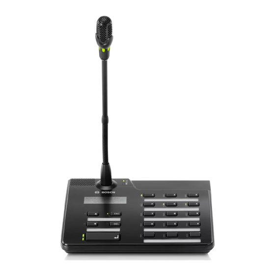
| System overview PAVIRO Call Stations System overview See the table on the following pages for an explanation of the numbers in the top view figures. Figure 3.1: Top view PVA-15CST call station 2018.04 | 04 | F01U306899 Bosch Security Systems... - Page 13 PAVIRO Call Stations System overview | en Figure 3.2: Top view PVA-15ECS call station Bosch Security Systems 2018.04 | 04 | F01U306899...
- Page 14 Illuminates red if the system indicator light is in the voice alarm condition state. Combined fault Illuminates yellow if a fault warning indicator occurs. light Power indicator Illuminates green if the light power supply is on. 2018.04 | 04 | F01U306899 Bosch Security Systems...
- Page 15 DEL button - (no default configuration). ▼ button Stops a live audio signal, with indicator light. ↵ button For announcements to selected zones, with indicator light. See also – Retrofit options, page 21 Bosch Security Systems 2018.04 | 04 | F01U306899...
-
Page 16: Bottom
Description EXT OUT Connection for call station extension port CST BUS Connection to controller port LINE port Connection for external audio devices or a PTT button MIC port Connection for external microphone 2018.04 | 04 | F01U306899 Bosch Security Systems... -
Page 17: Parts Included
Parts included | en Parts included Quantity Component PVA-15CST or PVA-15ECS call station Patch cable (3 meters) Blank paper strips Strain relief (bracket) Screws for strain relief Cover release tool Operation manual Important safety instructions Bosch Security Systems 2018.04 | 04 | F01U306899... -
Page 18: Installation
(button 1 = zone 1, button 2 = zone 2 etc.) Call in selected zones/groups, ↵ default priority 50 Switches system on/off, default ▲ priority 40 Stops an active audio signal, ▼ default priority 69 2018.04 | 04 | F01U306899 Bosch Security Systems... - Page 19 If several call stations need to operate with a single controller, each call station must be assigned a unique CAN address (1-16). Subsequently, if the CAN address changes, the configuration has to be changed as well. Bosch Security Systems 2018.04 | 04 | F01U306899...
-
Page 20: Button Labeling
Insert the labeled paper strips into the label fields. Reattach the transparent cover: Align the bottom cover snaps with the holes in the call station housing, then push the top cover snaps gently and equally into the holes. 2018.04 | 04 | F01U306899 Bosch Security Systems... -
Page 21: Retrofit Options
If an error occurs, this is indicated in the error log of the system. Figure 5.1: PVA-1EB Assembly Note the following information regarding installation of the PVA-1EB in the call station. Notice! An application note for the PVA-1EB is available. Bosch Security Systems 2018.04 | 04 | F01U306899... - Page 22 Perform any follow-up work that may be required to the installation location (e.g. filing, trimming). 2018.04 | 04 | F01U306899 Bosch Security Systems...
-
Page 23: Key Switch
Unscrew the call station baseplate (4 screws) Carefully remove the baseplate from the upper part, starting on the top left corner of the call station. Unplug the connecting cable from the CN1 plug connector Bosch Security Systems 2018.04 | 04 | F01U306899... - Page 24 1 (red) and 4 (green) must be cut as close to the cut-off point as possible and isolated. The two internal cables 2 (green) and 3 (green) must be soldered to switch connections 1 and 2. The polarity is not important. 2018.04 | 04 | F01U306899 Bosch Security Systems...
- Page 25 CN201/CN202/CN203 on the circuit board 11. Plug the connecting cable into CN1 again 12. Carefully re-attach the call station baseplate 13. Re-connect the connections 14. Configure the button using the software Bosch Security Systems 2018.04 | 04 | F01U306899...
-
Page 26: Connection
The CST BUS port is used to connect the call station with a controller. This is an 8-pin RJ-45 port that assigns the power supply, control interface (CAN bus), and audio interface. The call station must be connected to the respective wall-mount 2018.04 | 04 | F01U306899 Bosch Security Systems... - Page 27 If the voltage drop is higher than 3 V DC, the minimum supply voltage of the controller has to be increased to ensure the minimum supply voltage of the call station. Bosch Security Systems 2018.04 | 04 | F01U306899...
-
Page 28: Line Port
The MIC interface allows a second microphone to be connected. A conventional "PC microphone" (V = 3.3 V) can be connected. The following diagram shows the assignment of a 3.5 mm stereo jack plug for connection to the MIC jack. 2018.04 | 04 | F01U306899 Bosch Security Systems... -
Page 29: Ext Interface
This socket is primarily used to connect a call station extension. To do so, connect the call station extension to the EXT socket of the call station via the connecting cable provided. Bosch Security Systems 2018.04 | 04 | F01U306899... -
Page 30: Configuration
31 Program 16 Volume Date/Time Set Language Indicator Test LCD Contrast Brightness Monitor Volume CST Setup Input See section Password Setup menu, page 34 CST Setup CAN Address Menu CAN Baudrate Termination 2018.04 | 04 | F01U306899 Bosch Security Systems... -
Page 31: Main Menu
If zones have already been assigned to the program, the green LEDs on the selection buttons show the selected zones/groups. By pressing the selection buttons, the required zones/groups can be selected. This is indicated by the corresponding green LEDs. Bosch Security Systems 2018.04 | 04 | F01U306899... - Page 32 Use the 0–9 buttons on the call station to input entries. Pressing the ↵ button accepts the setting selected, and returns the user to the Main Menu. 2018.04 | 04 | F01U306899 Bosch Security Systems...
- Page 33 CST Setup Pressing the ↵ button takes the user to the Password dialog. Use the 0–9 buttons on the call station to input entries. Passwords are used to activate call station options. Bosch Security Systems 2018.04 | 04 | F01U306899...
-
Page 34: Setup Menu
Termination must be activated on the call station that is connected to the end of the CAN bus. Pressing the ↵ button accepts the setting selected, and returns the user to the CST Setup Menu. 2018.04 | 04 | F01U306899 Bosch Security Systems... - Page 35 Pressing the ▲ or ▼ button activates or deactivates the indication of the Date/Time menu item in the menu. Pressing the ↵ button accepts the setting selected, and returns the user to the CST Setup Menu. Bosch Security Systems 2018.04 | 04 | F01U306899...
-
Page 36: Operation
System is switched on and ready for operation Flashing green System has been switched on and is booting up (activation process) Pressing the button does not ▼ do anything – the action cannot be stopped 2018.04 | 04 | F01U306899 Bosch Security Systems... - Page 37 A call that has already started will be interrupted by the higher priority POWER The call station power supply has been deactivated/ interrupted Illuminated green The call station power supply is functioning correctly Bosch Security Systems 2018.04 | 04 | F01U306899...
- Page 38 If an error occurs in the system, this is displayed on the call station as follows: – The FAULT indicator light flashes, and a signal tone is sounded via the built-in loudspeaker – The fault is displayed in the LC display 2018.04 | 04 | F01U306899 Bosch Security Systems...
- Page 39 – The FAULT indicator light signals an error in the system for as long as it exists The fault display and signal tone must be configured via the configuration in IRIS-Net. Bosch Security Systems 2018.04 | 04 | F01U306899...
-
Page 40: Functions
Pressing this button stops a When navigating ▼ live audio signal (chime, alarm, through the menu, text). The precise function can this button is be configured in the IRIS-Net used to scroll software. down. 2018.04 | 04 | F01U306899 Bosch Security Systems... - Page 41 (see section Indicators, page 36). The buttons can be assigned a special function or no function (no assignment). The functions are assigned during configuration with a PC. Depending on the Bosch Security Systems 2018.04 | 04 | F01U306899...
- Page 42 The corresponding green indicator light will come – To disable a zone or zone group that has already been selected, press the corresponding selection button again. The relevant green indicator light will go out. 2018.04 | 04 | F01U306899 Bosch Security Systems...
- Page 43 To remove all zones or zone groups from the list, press the * key for longer than 3 seconds. – To recall the last selected zone or zone group, press the # key for longer than 2 seconds. Bosch Security Systems 2018.04 | 04 | F01U306899...
- Page 44 “all” is selected. – Hold the ↵ button down until the end of the announcement. The ↵ indicator light behaves in the same way as during the selection call. 2018.04 | 04 | F01U306899 Bosch Security Systems...
- Page 45 Alarm buttons can be configured in such a way that an alarm signal is only transmitted to certain zones/groups that have been previously selected. As with the selection call, the zones/ groups to which an alarm is to be transmitted must be selected Bosch Security Systems 2018.04 | 04 | F01U306899...
- Page 46 The volume levels can also be controlled via the Up/Down buttons. More information on this topic can be found in the IRIS-Net documentation. 2018.04 | 04 | F01U306899 Bosch Security Systems...
-
Page 47: Maintenance
PAVIRO Call Stations Maintenance | en Maintenance The call station does not require any special maintenance. For hygienic reasons and a clean appearance, the call station can be cleaned with a soft cloth. Bosch Security Systems 2018.04 | 04 | F01U306899... -
Page 48: Technical Data
Indicator lights Power (green), Fault (yellow), Alarm (red) Green or yellow LED per pre- programmed menu button Green and red LED per programmable zone/function LC display Back-lit LC display (122 ✕ 32 pixel) 2018.04 | 04 | F01U306899 Bosch Security Systems... - Page 49 Width x Depth) (without microphone) 66 mm (without microphone) E1, E2, E3 Net weight (PVA-15CST) 0.6 kg Net weight (PVA-15ECS) 1.64 kg Shipping weight (PVA-15CST) 1.1 kg Shipping weight (PVA-15ECS) 1.82 kg Bosch Security Systems 2018.04 | 04 | F01U306899...
- Page 50 – ICES-003 - This class B digital apparatus complies with Canadian ICES-003. Cet appareil numérique de la classe B est conforme à la norme NMB-003 du Canada. 2018.04 | 04 | F01U306899 Bosch Security Systems...
-
Page 51: Circuit Diagram
PAVIRO Call Stations Technical data | en 10.1 Circuit diagram Bosch Security Systems 2018.04 | 04 | F01U306899... -
Page 52: Dimensions
| Technical data PAVIRO Call Stations 10.2 Dimensions The PVA-15CST and PVA-15ECS call stations have the same external dimensions. Only the PVA-15CST call station is shown in the following figure: 2018.04 | 04 | F01U306899 Bosch Security Systems... -
Page 53: Appendices
Mount the connecting plate with 4 screws (Torx T10), please note the TOP symbol on the connecting plate. Insert connecting cable into the EXT socket of the call station or call station extension (the connector will click into place). Bosch Security Systems 2018.04 | 04 | F01U306899... - Page 54 If a call station extension is replaced in a call station system that has already been configured, the replacement device must be assigned the address of the replaced device via the DIP switch EXTENSION ADDRESS. DIP Switch Comment Disconnected Tab. 11.1: Extension address 2018.04 | 04 | F01U306899 Bosch Security Systems...
- Page 56 Bosch Security Systems B.V. Torenallee 49 5617 BA Eindhoven Netherlands www.boschsecurity.com © Bosch Security Systems B.V., 2019...
Need help?
Do you have a question about the PAVIRO Series and is the answer not in the manual?
Questions and answers
vad kan jag hitta mjukvara