Advertisement
KNOW YOUR PRODUCT
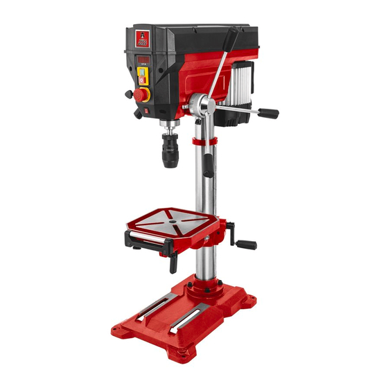
DIGITAL
DRILL
PRESS
• POWERFUL 750W
INDUCTION MOTOR
• PRECISION SPEED
CONTROL
• EASY SPEED
ADJUSTMENT
INSTRUCTION MANUAL
WARNING: Read all safety warnings and all instructions. Failure to follow the
warnings and instructions may result in electric shock, fire and/or serious injury.
Save all warnings and instructions for future reference.
0319
Advertisement
Table of Contents

Related Manuals for Full Boar FBDDP-7500


Summary of Contents for Full Boar FBDDP-7500
- Page 1 KNOW YOUR PRODUCT DIGITAL DRILL PRESS • POWERFUL 750W INDUCTION MOTOR • PRECISION SPEED CONTROL • EASY SPEED ADJUSTMENT INSTRUCTION MANUAL WARNING: Read all safety warnings and all instructions. Failure to follow the warnings and instructions may result in electric shock, fire and/or serious injury. Save all warnings and instructions for future reference.
-
Page 2: Specifications
SPECIFICATIONS - MODEL NO. FBDDP-7500 Voltage: 220 – 240V ~ 50Hz Motor rating: 750 W (S2 15min) Motor speed: 1480/min Output speed: 450 – 2,500/min Drill chuck mount: B 16 Spindle taper: Drill chuck: Ø 1 – 16 mm Throat:... - Page 3 KNOW YOUR PRODUCT (cont.)
-
Page 4: Table Of Contents
TABLE OF CONTENTS SPECIFICATIONS............Page 02 KNOW YOUR PRODUCT........... Page 02 INTRODUCTION............Page 05 SAFETY INSTRUCTIONS........... Page 05 ASSEMBLY..............Page 10 ADJUSTMENTS............Page 15 OPERATION............... Page 20 MAINTENANCE............Page 22 TROUBLE SHOOTING..........Page 24 DESCRIPTION OF SYMBOLS........Page 26 CONTENTS..............Page 27 WARRANTY.............. -
Page 5: Introduction
INTRODUCTION Congratulations on purchasing a Full Boar Digital Bench Drill Press. Your Full Boar Digital Drill Press FBDDP-750 is designed for drilling large or small holes in metal, plastic, wood and similar materials. Heavy duty cast iron base and table provide solid and stable work surface. - Page 6 GENERAL SAFETY INSTRUCTIONS WARNING! Read all instructions. Failure to follow all instructions listed below may result in electric shock, fire and/or serious injury. The term “Power Tool” in all of the warnings listed below refers to your mains operated (corded) power tool or battery operated (cordless) power tool.
- Page 7 GENERAL SAFETY INSTRUCTIONS (cont.) d. Remove any adjusting key or wrench before turning the power tool on. A wrench or a key left attached to a rotating part of the power tool may result in personal injury. e. Do not overreach. Keep proper footing and balance at all times. This enables better control of the power tool in unexpected situations.
- Page 8 ADDITIONAL SAFETY RULES FOR BENCH DRILLS IMPORTANT! When using the equipment, a few safety precautions must be observed to avoid injuries and damage. Please read the complete operating manual with due care. Keep this manual in a safe place so that the information is available at all times.
- Page 9 ADDITIONAL SAFETY RULES FOR BENCH DRILLS 11. Avoid unintentional start-up: Ensure that switch is turned off when plugging the plug into the socket. 12. Keep an eye on your work: Always keep an eye on your machine and the object you are working on.
-
Page 10: Assembly
ASSEMBLY WARNING! During assembly ensure the bench drill is disconnected from the power supply. WARNING! Some parts are heavy, two-person lift may be required to avoid injury. Assembling the digital drill press 1. Carefully remove contents from the packaging. 2. Select a firm, level surface on which to assemble the bench drill. 3. - Page 11 ASSEMBLY (cont.) 6. Slide the gear rack (26) all the way down until it locates into the base of the column (3) (Fig. 4). Fig. 4 7. Slide the locking ring (25), tapered side facing down so that it rests lightly on the gear rack (26). Tighten the fitted grub screw to secure locking ring (25) in position with hex key.
- Page 12 ASSEMBLY (cont.) 10. Fit the main Housing (1) to the column (3). Align the head so that it is horizontal to the base (Fig. 8). Fig. 8 11. Fasten the main Housing (1) in position by tightening the 2 fitted grub screws on both sides (Fig. 9), with hex key. Fig.
- Page 13 ASSEMBLY (cont.) 13. Force the arbor (33) into the top of the drill chuck (16) by hand, using reasonable force (Fig. 11). Fig. 11 IMPORTANT: Before you mount the drill chuck onto the spindle, check that both parts are free of dirt and grease. This ensures optimal transmission of power. 14.
- Page 14 ASSEMBLY (cont.) 18. Before you use the digital drill press for the first time it must be mounted in a stationary position on a firm surface. Use four mounting holes (21) in the base (30) to do this. Ensure that the machine is freely accessible for operation, adjustment and maintenance (Fig.
-
Page 15: Adjustments
ADJUSTMENTS Table height adjustment 1. Loosen the table support lock (Fig. 17). 2. Rotate the table adjustment handle (27) to set the desired drill table (18) height. Tighten the table lock to secure the drill table (18) in position (Fig. 18). Fig. - Page 16 ADJUSTMENTS (cont.) Roller support adjustment 1. Loosen the thumb screws to extend the roller support (19). 2. Re-tighten thumb screw when the roller support (19) is in the desired position (Fig. 23). WARNING! Use a suitable clamping device to secure a workpiece in position. Never hold the workpiece in place with your hand! Ensure that the workpiece cannot rotate.
- Page 17 ADJUSTMENTS (cont.) Installing straight shank drill bit WARNING! Always ensure the digital drill press is switched off and disconnected from the power supply before installing/changing drill bits. 1. Make sure that the power plug is removed from the socket-outlet before changing bits. WARNING! Only cylindrical bits with the stipulated maximum shaft diameter may be clamped in the drill chuck (9) (Fig.
- Page 18 ADJUSTMENTS (cont.) Presetting the drilling depth The drilling spindle has a swivelling scale ring for setting the drill depth. Only adjust the setting when the machine is at a standstill. Make sure that the power plug is removed from the socket-outlet before adjusting the setting. To stop spindle (and bit) at a desired depth:- 1.
- Page 19 ADJUSTMENTS (cont.) 4. Insert the drift key (34) into the slot and tap firmly with a soft face hammer until it releases, taking care as you do so to ensure that the chuck does not land on the floor. (Ensure the chuck jaws are wound all the way up to prevent damage) (Fig.
-
Page 20: Operation
OPERATION WARNING! The power supply for this product should be protected by a residual current device (rated at 30mA or less). A residual current device reduces the risk of electric shock. The bench drill is equipped with a no-volt trip that is designed to protect the operator from an undesired restart following a power outage. - Page 21 OPERATION (cont.) Working speed table Ensure that you drill at the proper speed. Drill speed is dependent on the diameter of the drill bit and the material in question. The table below acts as a guide only for selecting the proper speed for various materials. Note: The drill speeds specified are a guide only.
-
Page 22: Maintenance
MAINTENANCE WARNING! Ensure the drill press is switched off and disconnected from the power supply before performing any maintenance or cleaning. • Ball bearings are packed with grease at the factory. No further lubrication of bearings is required. • Lubricate all moving parts periodically. Wipe the column, table and base with an oily cloth to minimise corrosion. - Page 23 MAINTENANCE (cont.) 5. Pry the V-belt off of the smaller drive pulley by pulling up the belt on one side and slowly turning the pulleys (Fig. 39). Fig. 39 6. The drive pulley comprises two disks that are pressed together via a spring. If the V-belt does not exhibit enough play to remove it, gently press the bottom half of the drive pulley down to slacken the V-belt (Fig.
-
Page 24: Trouble Shooting
TROUBLE SHOOTING Problem Cause Solution Drill press will Power cord not Ensure that the power cord not start. connected to the mains is connected to the mains power supply. power. Power fault. Check the mains power supply. Safety guard (8) not fitted Fit and place safety guard (8) or in the open position. - Page 25 NOTES...
-
Page 26: Description Of Symbols
DESCRIPTION OF SYMBOLS Read instruction manual Wear eye and ear protection CARING FOR THE ENVIRONMENT Power tools that are no longer usable should not be disposed of with household waste but in an environmentally friendly way. Please recycle where facilities exist. Check with your local council authority for recycling advice. -
Page 27: Contents
CONTENTS 1x Main Housing 1x Column 1x Drill table & roller support 1x Base 1x Table support 3x Feed handles 1x Safety guard 1x Rail 1x Drill chuck 1x Table adjustment handle 4x Bolt, washer & spring washer 2x Safety guard screws 1x Screw &...
Need help?
Do you have a question about the FBDDP-7500 and is the answer not in the manual?
Questions and answers