Table of Contents
Advertisement
Quick Links
Installation Instructions for Thinkware VHL3Z-19G490-C & VHL3Z-19G490-D
1 Locate the OBD II connector inside the vehicle and remove it from the mounting surface.
For this it may be necessary to remove the two 8mm nuts that fix it to the bottom of the
board (Fig a) or press the two clips, with the tool of the lining of the plastic board, which
secure it behind the plastic cover protective (Fig b)
2 Connect the male end of the HWK-TW01-HAR Plug-n-Play to the OBD II factory
connector of the vehicle (Fig A)
3 Secure the OBD II connector with the harness using one of the straps cut the excess of
the strap (Fig B)
4 In the case of the bolt and nut assembly: place the left flange of the connector on the
factory left bolt, and replace and adjust the nut removed in step 1. Secure the right
flange of the connector under the board using the included self-tapping screw (FIG C).
In the case of clip mounting: place the body of the harness in the opening of the board
and secure the connector to the board using the included self-tapping screws (Fig D).
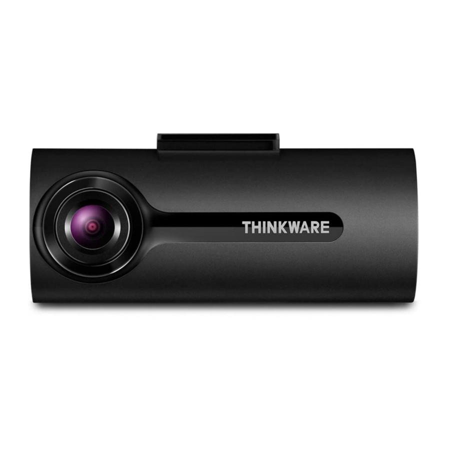
Dash Cam
Advertisement
Table of Contents

Subscribe to Our Youtube Channel
Related Manuals for Thinkware VHL3Z-19G490-C


Summary of Contents for Thinkware VHL3Z-19G490-C
- Page 1 Installation Instructions for Thinkware VHL3Z-19G490-C & VHL3Z-19G490-D Dash Cam 1 Locate the OBD II connector inside the vehicle and remove it from the mounting surface. For this it may be necessary to remove the two 8mm nuts that fix it to the bottom of the board (Fig a) or press the two clips, with the tool of the lining of the plastic board, which secure it behind the plastic cover protective (Fig b) 2 Connect the male end of the HWK-TW01-HAR Plug-n-Play to the OBD II factory connector of the vehicle (Fig A) 3 Secure the OBD II connector with the harness using one of the straps cut the excess of the strap (Fig B) 4 In the case of the bolt and nut assembly: place the left flange of the connector on the factory left bolt, and replace and adjust the nut removed in step 1. Secure the right flange of the connector under the board using the included self-tapping screw (FIG C). In the case of clip mounting: place the body of the harness in the opening of the board and secure the connector to the board using the included self-tapping screws (Fig D).
- Page 2 5 Remove the saddle panel from the A pillar: for this it may be necessary to remove the 2 10mm bolts. Pass the Thinkware power cable to the driver's side of the vehicle, going up the A-pillar (Fig E) and along the front edge of the vehicle's casing (Figures F and G) so that it is clear of the casing through the hole factory that is located above the rearview mirror. NOTE: If passing the wax cables from the side airbag, make sure they do not impede the ability to deploy the airbag in case of an accident 6 Clean and dry the installation site with a cloth with alcohol before placing the camera. Slide the camera inside the bracket and secure it to the windshield using the self- adhesive pad pre-installed in the bracket (FIG A). Be sure to mount the dashboard behind the rearview mirror so that it does not obstruct the driver's vision, taking care not only that the lens is as close to the center of the vehicle as it is as level as possible. It may be necessary to connect to the dashboard with the Thinkware smart phone application in order to adjust the image up or down until it is acceptable. ...
- Page 3 7 Wind and secure any excess cable (Fig B) 8 Place the vehicle ignition in the off position, connect the IGN-3F to the 10-pin Molex connector located on the HWK-TW01-HAR (Fig C). 9 Once the ignition of the vehicle is off and the IGN-3F is plugged in, the LED should emit a constant flashing light. The LED will go from the blinking state to a continuous ON light once the vehicle is started. When the light is ON continuously, an ignition phantom signal will be sent to the dashboard to turn on, and it will stay on during a start / stop sequence, the LED and the dashboard will turn off after 2 minutes, 30 seconds from the vehicle's shutdown. ...
- Page 4 10 Secure the connection between the module and the factory OBD II connector that is under the dashboard or on the side panel with a strap so that it does not impede the ability of the airbag to deploy in the event of an accident. 11 Make sure that all vehicle trimmings removed during the previous steps of the installation have been repositioned. The steps below are only necessary if the optional rear camera is installed 1. Using the above techniques, insert and route the cable through the casing from the front camera to the mounting position of the rear camera. The cable will have a label that indicates which side should go towards the front of the vehicle. See the slots A to D for more information. 2. Clean and dry the installation place with a cloth before placing the camera. Place the camera in the rear window using the adhesive provided with the camera. Remember not to place the camera in a place where it may interfere with the rearview mirror. It may be necessary to connect to the dashboard using the Thinkware smart phone application to verify that the orientation of the image is correct and that the entire rear part of the vehicle enters the image. See figures E and F for more information. 3. Make sure that all vehicle trimmings removed during the previous steps of the installation have been repositioned.
Need help?
Do you have a question about the VHL3Z-19G490-C and is the answer not in the manual?
Questions and answers