Table of Contents
Advertisement
Quick Links
Advertisement
Table of Contents

Related Manuals for DigiBird DB-RC4 v2


Summary of Contents for DigiBird DB-RC4 v2
- Page 2 ® All rights reserved by DigiBird...
-
Page 3: Table Of Contents
NOTICES…………………………………………………………………………………………………………………4 I. Introduction……………………………………………………………………………………………………………6 1.1 About This Guide………………………………………………………………………………………………………………6 1.2 About the DB-RC4 v2 Video Wall Controller…………………………………………………………………………………6 1.3 Key Features of the DB-RC4 v2 Video Wall Controller……………………………………………………………………6 1.4 Video Wall Layout Examples…………………………………………………………………………………………………7 II. The DB-RC4 v2 Hardware……………………………………………………………………………………………8 2.1 Unpacking and inspection……………………………………………………………………………………………………8 2.2 Hardware Overview……………………………………………………………………………………………………………8 2.2.1 Technical Specification……………………………………………………………………………………………………9... - Page 4 5.6.4 Layering the Capture Regions…………………………………………………………………………………………35 5.6.5 Flip Horizontally or Vertically……………………………………………………………………………………………36 5.6.6 Capture Regions Properties……………………………………………………………………………………………37 5.6.7 How to Calculate the Pixel Size and Position of a Capture Region………………………………………………37 5.7 Adding a Device (DB-RC4 v2)…………………………………………………………………………………………………39 5.8 Apply……………………………………………………………………………………………………………………………41 5.9 Refresh…………………………………………………………………………………………………………………………41 5.10 Configuration Template Management……………………………………………………………………………………42 5.11 EDID Management…………………………………………………………………………………………………………42...
-
Page 5: Notices
In no event will DigiBird be liable for direct, indirect, special, incidental, or consequential damages resulting from any defect or omission in this manual, even if advised of the possibility of such damages. Nor shall DigiBird be liable for any compensation for any income, information, business reputation or any anticipated saving cost for the users. - Page 6 Safety Precautions To prevent damage to your DigiBird product or injury to personnel operating the equipment, please read the safety precautions prior to operation. Make sure your PC configuration meets the minimum requirements indicated in this manual. Make sure the operating system is compatible with the requirements indicated in this manual.
-
Page 7: Introduction
I. Introduction Thank you for choosing the DigiBird DB-RC4 v2. Before you begin configuring your DB-RC4 v2 for the first time, please read completely through the document to become familiar with its features. This section gives an overview of the user guide and features of the DB-RC4 v2 Video Wall Controller and Control &... -
Page 8: Video Wall Layout Examples
1.4 Video Wall Layout Examples Figure 1.4 Video Wall Layout Examples ® All rights reserved by DigiBird... -
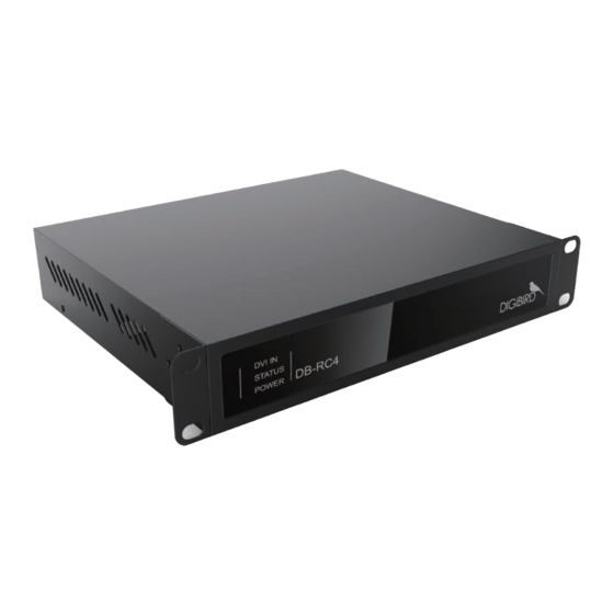
Page 9: The Db-Rc4 V2 Hardware
The DB-RC4 v2 enclosure will arrive boxed with internal foam for protection during shipping. You are encouraged to retain the box and all packing material so the unit can be returned in the unlikely event that repairs should ever become necessary. -
Page 10: Front Panel
USB Type B Port: This USB Type B port is compatible with USB 1.0 and 2.0. The USB port is used to connect the DB-RC4 v2 to your control PC. A USB Type A to Type B cable is supplied with the DB-RC4 v2. The DB-RC4 v2 can be controlled via the USB port while using the windows-based software. -
Page 11: S I D E Vi E
Research & Development, Manufacturing and Sales DVI-I Output Port # 1 to # 4: The four black DVI-I Output ports are used to connect the DB-RC4 v2 to the output monitors or displays. The DVI-I outputs support both DVI and analog RGB (VGA) signals. -
Page 12: Db-Rc4 V2 Hardware Installation
Layout Mode Duplicate Mode and No Rotation The default settings can be modified with the DB-RC4 v2 Video Wall Control and Design Software (RCS). Refer to the software section in the DB-RC4 v2 user guide that came with your product. -
Page 13: Connection Diagram
↑ , down ↓ , left ← and right → arrows on the keyboard. • The DB-RC4 v2 Control and Design Software provides a monitor database, and most well-known manufacturers are already included at launch. It also allows users to add their own monitors manually. -
Page 14: Computer System Requirements
Custom video wall configurations can be saved as templates for future recall. 3.1 Computer System Requirements For the DB-RC4 v2 Control and Design Software to function correctly and reliably, it must be installed on a computer that meets or exceeds the following criteria:... -
Page 15: Installing The Software
3.2.2 Installing the Software The Control and Design Software installation file is provided on a CD with your DB-RC4 v2 (it is also available for download from the DigiBird website at www.digibirdtech.com). Install the program on your computer in the following way: Copy the file “RCSCtrl_2.0”... - Page 16 Figure 3.2.2 D: Choose install location Figure 3.2.2 E: Finish ® All rights reserved by DigiBird...
-
Page 17: Uninstalling The Software
Open the Start Menu by clicking the Start button and then click “All Programs” → “ RC4 Control and Design Software” → “Uninstall”, as shown: Figure 3.2.3 A: Uninstall Follow the instructions on the Uninstall Wizard to complete the uninstall as shown in the steps below: ® All rights reserved by DigiBird... - Page 18 Figure 3.2.3 B: Uninstall Figure 3.2.3 C: Uninstallation completed ® All rights reserved by DigiBird...
-
Page 19: Running The Software
& Image Processing Research & Development, Manufacturing and Sales IV. Running the Software Once the DB-RC4 v2 Control and Design Software has been installed, the user can run the application with any of the following methods: • Double-click the DB-RC4 v2 icon (shortcut) on the desktop. -
Page 20: Software Overview
5.1 Software Overview Prior to setup of the positions of monitors and capture regions, the user needs to be conversant with the software. The DigiBird DB-RC4 v2 Control and Design Software application window contains the following elements: Figure 5.1 A: Software Overview Menu Bar: includes Start Menu and Customized Toolbars. -
Page 21: Mounting Wall Size Setting
To do this, hover your mouse cursor over the Physical Layout Window, and then right-click on the window background. The Mounting Wall Size menu will appear. Left click to perform setup as shown in the figures below: ® All rights reserved by DigiBird... - Page 22 Figure 5.2 B: Mounting Wall Size Figure 5.2 C: Height and width ® All rights reserved by DigiBird...
-
Page 23: Input Resolution Settings
Hover your mouse cursor over the background image of the Capture Regions Window and then right-click on the background. The Input Resolution Settings menu will appear. Left-click it to enter the Input Resolution Settings, as shown in the figures below: see figure 5.3 A. Figure 5.3 A: Default input resolutions ® All rights reserved by DigiBird... - Page 24 After filling in the values of the resolution timing parameters, click “Create Custom Resolution” and then press “OK”. The custom resolution will be created, as shown in the figure 5.3 C. Figure 5.3 C: Create custom resolution ® All rights reserved by DigiBird...
-
Page 25: Monitor Settings
Research & Development, Manufacturing and Sales When clicking the “OK” button, a command will be sent to the DB-RC4 v2 device to adjust the input resolution. If it fails to send the command, an information window will appear, as shown in the figure below: Figure 5.3 D: The operation failed. - Page 26 Manufacturer and Models dropdown lists to choose a specific, listed monitor. Refer to the following figures for reference: Figure 5.4.1 C: Manufacturer Dropdown List Figure 5.4.1 C: Models Dropdown List After the manufacturer and model selection, data will appear in the Monitor Properties window. The Monitor Properties ® All rights reserved by DigiBird...
-
Page 27: Adding New Monitors
After filling in the required values, click the Save Details button at the bottom left of the Monitors setting window. The new monitor will appear in the manufacturer and models dropdown list, as shown in the figure below: ® All rights reserved by DigiBird... -
Page 28: Delete A Custom Monitor
5.4.3 Delete a Custom Monitor Select the custom manufacturer and model and click the Delete button. The custom monitor will be deleted from the monitor database, as shown in the figure below: ® All rights reserved by DigiBird... -
Page 29: Physical Layout Design And Settings
Physical Layout window. Right click on a monitor to bring up the context menu. This allows you to change its rotation or to sync the operation to the Capture Regions, as shown in the figures below. ® All rights reserved by DigiBird... - Page 30 Left-click the slider in the zoom bar and drag it to the left to zoom out; drag to the right to zoom in c. Sliding the mouse wheel or row-resize cursor d. Using the col-resize Figure 5.5 B: Display proportion ® All rights reserved by DigiBird...
-
Page 31: Toolbar For Physical Layout Settings
Below is an example of a video wall configuration. Monitor #1 is rotated clockwise 45°; Monitor #2 is rotated clockwise 135°; Monitor #3 is rotated clockwise 315°; Monitor #4 is rotated clockwise 225°. This kind of video wall configuration is commonly referred to as a “Windmill” layout: ® All rights reserved by DigiBird... -
Page 32: Sync To Capture Regions Icon
Figure 5.5.4 A: Sync to capture regions Right clicking on the Physical Layout window will make the context menu appear, which includes the following options: Centered, Sync to Capture Regions and Mounting Wall Size. ® All rights reserved by DigiBird... - Page 33 Research & Development, Manufacturing and Sales Figure 5.5.4 B: Context menu bar of Physical Layout Right click on a monitor in the Physical Layout window. The context menu will appear, as shown in the figure below. ® All rights reserved by DigiBird...
-
Page 34: Capture Regions Settings
Use the col-resize or row-resize cursor • Hover the mouse cursor over the blank area of the Capture Regions window, right click, and the context menu will appear Figure 5.6.2 A: Dropdown list and Zoom Bar ® All rights reserved by DigiBird... -
Page 35: Context Menu Of The Capture Regions
Research & Development, Manufacturing and Sales Figure 5.6.2 B: zoom in/out 5.6.3 Context Menu of the Capture Regions Hover the mouse cursor over the capture region and right click. The context menu will appear, as shown below: ® All rights reserved by DigiBird... -
Page 36: Layering The Capture Regions
No. 1 at the bottom, layering sequentially to monitor No. 4 at the top. The user can change the layer priority of the capture regions by selecting Top Layer, Bottom Layer, Move Up and Move Down. Below is an example of how to use the layering function to design a video wall: ® All rights reserved by DigiBird... -
Page 37: Flip Horizontally Or Vertically
Capture Regions window. 5.6.5 Flip Horizontally or Vertically Choose Flip Horizontally or Flip Vertically from the above context menu. The resulting display of the monitors should look like the following: Figure 5.6.5 Flip horizontally/ vertically ® All rights reserved by DigiBird... -
Page 38: Capture Regions Properties
Below is a simple example to illustrate this calculation process: Two Acer S221HQL monitors are positioned on the Mounting Wall. There is no gap between the two monitors, as shown in the following figure: ® All rights reserved by DigiBird... - Page 39 NOTE: The default input resolution is 1920 × 1080@60Hz. 1920 pixels/982 mm= 1.9552 pixels/mm Third, calculate how many horizontal pixels the No. 2 monitor should have by using the following formula: Viewable Width × 1.9552 pixels/mm= 477mm × 1.9552 pixels/mm= 932 pixels ® All rights reserved by DigiBird...
-
Page 40: Adding A Device (Db-Rc4 V2)
Figure 5.6.7 B: Position 5.7 Adding a Device (DB-RC4 v2) If large video walls are required for your solution (more than four monitors or displays), you can add additional DB-RC4 v2 devices by connecting them with a DVI splitter and then adding them on the software. The DVI splitter distributes the input source across all of the connected DB-RC4 v2s. - Page 41 Figure 5.7 A: Cascaded devices layout Add or delete the DB-RC4 v2 devices by clicking the Plus (+) icon or Subtract (-) icon on the Monitor Window, as shown below. After that, the selected monitors on the Physical Layout Window and the selected Capture Regions on the Capture Regions Window can be moved by clicking and dragging them.
-
Page 42: Apply
After setting up the Monitors and Capture Regions and connecting the DB-RC4 v2 hardware, click the “Apply” icon in the Toolbar. The software will send the configuration template to the device (DB-RC4 v2 hardware) and the configuration will take effect. -
Page 43: Configuration Template Management
The software supports EDID management by enabling the user to read the input EDID information and the output EDID information (Display side), and save the output EDID to the DB-RC4 v2 or perform a ‘Save As’, saving the EDID information to file. -
Page 44: Write Edid To Input
The software supports the writing of EDID information to the input. The user needs to click the “Read EDID” button prior to writing the EDID to the input. 5.11.3 Open EDID File Press “Open EDID File” to import the user-saved EDID file. ® All rights reserved by DigiBird... -
Page 45: Test
Figure 5.12 A: Test 5.13 Language The software is multilingual, currently supporting English, Chinese Simplified and Chinese Traditional. Figure 5.13 Language Selection 5.14 About Click the “About” icon to show the version and copyright information. ® All rights reserved by DigiBird...
Need help?
Do you have a question about the DB-RC4 v2 and is the answer not in the manual?
Questions and answers