Advertisement
s
WAC 11
Installation Instructions
Fig. 1
T
R
Fig. 2a
Fig. 2b
T
Y
R
Fig. 3
W
Q
Q
W
E
Y
NC T
T
-A +A
U
U I
O
NC
T
T -A
+A
Q
DS1
W
E
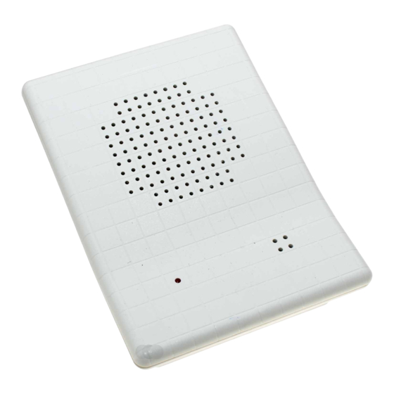
1. Product description
The WAC 11 is used to verify audio alarms. It is fitted with a
speaker and microphone. The audio signal is connected directly
to the central control unit via an audio module (e.g. WMA 11) or
via a WAC 12, which acts as a master.
2. Supply package
The WAC 11 UK package contains the following
-
One WAC 11
-
One WLC 11 UK language kit complete with:
- Installation instructions.
3. Mounting instructions
The WAC 11 is designed for mounting in dry indoor rooms.
To ensure good acoustics, note the following points.
- Mount 2 to 2.5 m above floor level.
- Maintain adequate distance from noise sources (ven ti la tion
openings, fans etc.).
- Direct towards the centre of the space to be monitored.
- Do not mount on vibrating surfaces.
- The maximum length of the audio connection between the
WAC 11 and central control unit is 200 m.
3.1 Opening the housing (Fig.1)
1 - Using screwdriver Q, press locking tab to release.
2 - Lift off cover W.
3.2 Product overview (Fig. 2)
- Knockouts Q, T for cable inlet.
- Knockouts W, E for attachment of housing.
- Knockout R for disconnection monitor screw.
- Speaker Y.
- WMC 11 circuit board U.
3.3 WMC 11 circuit board (Fig. 3)
- Audio connection O.
- Tamper output I
- Free terminal U
- LED W, flashes to outside during monitoring (microphone
active).
- Switch E for "microphone active" LED.
- Tamper switch Y.
- Microphone R.
- Potentiometer Q for speaker volume.
- Potentiometer T for microphone sensitivity.
Advertisement
Table of Contents

Related Manuals for Siemens WAC 11


Summary of Contents for Siemens WAC 11
-
Page 1: Installation Instructions
Installation Instructions 1. Product description The WAC 11 is used to verify audio alarms. It is fitted with a speaker and microphone. The audio signal is connected directly to the central control unit via an audio module (e.g. WMA 11) or via a WAC 12, which acts as a master. - Page 2 (e.g. WMA 11) (Fig. 5b). Where several WAC 11 are WAS 11 WAC 12 WAC/WAS 11 used, all WAC 11 must be connected directly to the WAC 12 (Fig. 5c) or to the central control unit (Fig. 5d) to obtain optimum performance. Fig. 5a 4.2 Tamper (Fig. 5a)
Need help?
Do you have a question about the WAC 11 and is the answer not in the manual?
Questions and answers