Table of Contents
Advertisement
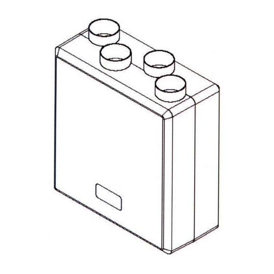
Mechanical Ventilation with Heat Recovery
Installation Instructions and User Manual
Commissioning Data: to be completed by the installer
Date of installation:
Configuration
Product Serial No:
Important: This multi speed unit requires Air Flow Rates to be adjusted on installation.
This manual must be kept by the householder.
MODEL: DV72
Left Hand
Right Hand
9041381- Issue 8 9/11
Advertisement
Table of Contents

Subscribe to Our Youtube Channel
Related Manuals for Airflow Duplexvent DV72


Summary of Contents for Airflow Duplexvent DV72
- Page 1 9041381- Issue 8 9/11 MODEL: DV72 Mechanical Ventilation with Heat Recovery Installation Instructions and User Manual Commissioning Data: to be completed by the installer Date of installation: Configuration Left Hand Right Hand Product Serial No: Important: This multi speed unit requires Air Flow Rates to be adjusted on installation. This manual must be kept by the householder.
-
Page 2: Table Of Contents
Index General Introduction 2.1. General 2.2. Overview of fitting the HR unit Installation Fitting the HR unit Important instruction Connecting ducts Connecting condensation drain Electrical connections Installation diagram / Fitting the unit User Maintenance Cleaning the filters by user Cleaning the heat exchanger by user Technical specifications Appliance data Expanded view of the HR unit... -
Page 3: General
1. General To maintain a healthy indoor environment, closely controlled ventilation is essential. There are many pollutants that will affect the indoor air quality: human body waste products in the shape of , dead skin, perspiration and moisture. Add to this the waste products of cooking (cooking smells), showering (moisture), gases from building materials and the waste products of pets. -
Page 4: Introduction
2. Introduction 2.1 General Duplexvent DV72 is a complete heat recovery unit to ensure optimum efficiency for your home. The unit can easily be set up for left or right hand operation. This can be done by changing the position of the condensation drain at the bottom of the unit. See figure 3 on page 4. -
Page 5: Installation
1. Dismantle the HR unit in accordance with Section 3 of this manual 2. Mounting plate: Mounted by means of stand-off feet, screws and plugs supplied (for vertical installation). Locate the hole positions, ensuring that there is enough space around the unit so that the duct work and the condensation drain can be fitted 3. -
Page 6: Connecting Ducts
3.3 Connecting ducts When the heat recovery unit has been installed the ducts can be fitted. The ducts to and from the home are on one side of the unit. The ducts to and from outside are on the opposite side. In order to prevent condensation on the outside of the exterior air inlet duct and the air outlet duct, both ducts must be insulated. - Page 7 Please follow the steps below: 1) Lay the unit on a flat level surface and remove the front half to the unit and put aside. 2) Carefully slide the heat exchanger out from the housing 3) Determine what side you want the condensate drain to be (see figure 3 for left and right hand positioning). If mounting the unit vertically the condensate hole needs to be in position shown at its lowest point to allow the condensate to run out (image shown for right hand installation).
- Page 8 4) Mark off with a pencil 173,5mm from the side of the unit (see figure 3) taking into account left or right hand configuration. From this point measure 52,5mm towards the rear of the unit – this is the point deemed to be the most effective location for the condensation drain.
- Page 9 Vertical Position Left Right Figure 3: Connection of HR unit to drain pipe Condensation drain: 22mm standard PVC Important Note: The unit can only be mounted horizontally with an additional condensation kit. This unit is not suitable for ceiling suspended installation. For more information please contact one of our sales representatives.
-
Page 10: Electrical Connections
3.5 Electrical connections The appliance must be earthed. All wiring must confirm to BS 7671: Latest edition IEE wiring regulations. This appliance is suitable for 230v ~ 50Hz single phase supply fused at 3 amps. This appliance is supplied with a mains flexible cable (PVC sheathed, 6-core 0.75mm A double pole switch having a minimum contact separation of 3.0mm must be used to provide isolation for the unit. - Page 11 Figure 4: Electrical Diagram...
-
Page 12: Installation Diagram / Fitting The Unit
3.6 Installation diagram / Fitting the unit 1. Pull the green front cover off the six Velcro fixings. 2. Place the unit flat on the floor and unscrew the four stud retaining screws - keep screws safe. 3. Without damaging the rubber seal, separate the moulded top half of the unit from the bottom half by pulling the casing straight forward. -
Page 13: User Maintenance
4. User Maintenance User maintenance is limited to periodically cleaning the filters and the heat recovery cube. The unit should not be used without filters. 4.1 Cleaning the filters by user Switch off the power supply Remove the filters Remove front panel Remove filter covers Vacuum the outside of the filters After cleaning replace filters... -
Page 14: Cleaning The Heat Exchanger By User
.2 Cleaning the heat exchanger by user Important: Switch off the power supply Unscrew the 4 screws on the front Remove front panel of the unit. Remove the front half of the unit Remove the heat exchanger Reassemble the unit taking care Clean the heat exchanger with not to damage the rubber seals warm, soapy water... -
Page 15: Technical Specifications
5. Technical specifications 5.1 Appliance data Switched External sensor EC Fan Speed settings selected on installation Low / Middle / High / (100% adjustable) Typical Ventilation Settings [m Rated power [W] Permissible duct/system resistance [Pa] 100 Pa at 200 m Maximum flow (Free Discharge) 280 m /hr (78 l/sec) -
Page 16: Expanded View Of The Hr Unit
5.2 Expanded view of the HR unit Please refer to guarantee terms for repair/replacement within the guarantee period. After expiry of the guarantee when ordering parts, be sure to mention the article number (see exploded view), the type of heat recovery appliance, serial number, production year and the name of the part: Example Appliance type : DV72... -
Page 17: Sap Appendix Q Test Results
SAP Appendix Q Testing Results Central mechanical supply and exhaust ventilation system packages with heat recovery used in a single dwelling Brand Name Airflow Model Duplexvent DV72 Model Qualifier (if applicable) Name Airflow Developments Ltd Lancaster Road Cressex Business Park... - Page 18 Results for SAP calculations (at minimum flow rate condition) This product has only been tested with rigid ductwork and the data are not applicable for SAP calculations if installed with flexible ductwork. Table Q2 – Systems with rigid ductwork only Energy Saving Specific Heat...
- Page 19 Table Q3 – Systems with flexible ductwork only Energy Saving Specific Heat Trust Best Exhaust terminal exchange speed Practice configuration power efficiency setting Performance (W/l/s) Compliant Kitchen + 1 additional wet room These figures are entered into either: (a) In the case of SAP software amended to SAP 2005 version 9.81 allowing direct entry of MVHR data, the SAP software, or (b) In the case of SAP software amended to SAP 2005 version 9.81 not allowing direct entry of MVHR data, the SAP Q MVHR Calculation Spreadsheet v9.81 and the results from the...
-
Page 20: Declaration Of Conformity
2006/95/EC (LVD) Applied Harmonised Standards: EN 60335-1:2002/A2:2006 EN 60335-2-80:2003/A1:2004 BS EN 308:1997 EN13141-7:2004 Airflow Developments Limited warrants that heat recovery appliances are manufactured from high quality materials and that continuous quality control ensures that they comply with the above directive. -
Page 21: Warranty
3. Repairs have not been attempted other than by Airflow’s service staff or 4. In Airflow’s sole discretion, the product is found to be faulty. If it were not found to be faulty, the product would be available for collection from the relevant Airflow premises within one calendar month and if it was not collected, it would be subsequently delivered by Airflow and a delivery charge will be made.
Need help?
Do you have a question about the Duplexvent DV72 and is the answer not in the manual?
Questions and answers