Table of Contents
Advertisement
Quick Links
AERCO INTERNATIONAL, Inc., 100 Oritani Dr., Blauvelt, NY 10913 USA
Installation and maintenance instructions
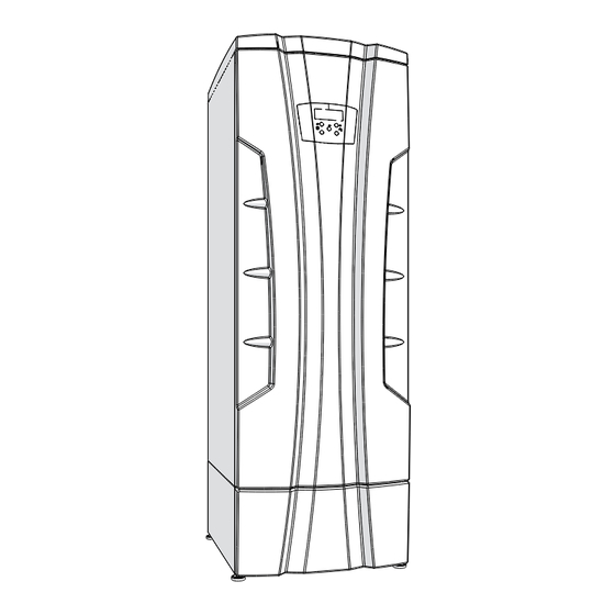
gas-fired condensing water heater series
INSTALLER, THESE INSTRUCTIONS TO BE AFFIXED ADJACENT TO THE HEATER
Instruction
AM - R
62403631 R03
No.
WARNING!!! This manual must only be
used by a qualified heating installer /
service technician. Read all instruc-
tions, including this manual, before
installing. Perform steps in the order
given. Failure to comply could result
in severe personal injury, death, or
substantial property damage.
Save this manual for future reference.
A
S
M
E
Advertisement
Table of Contents


Need help?
Do you have a question about the AM-R Series and is the answer not in the manual?
Questions and answers