Sign In
Upload
Manuals
Brands
Aerco Manuals
Water Heater
AM-R Series
Aerco AM-R Series Manuals
Manuals and User Guides for Aerco AM-R Series. We have
1
Aerco AM-R Series manual available for free PDF download: Installation And Maintenance Instructions Manual
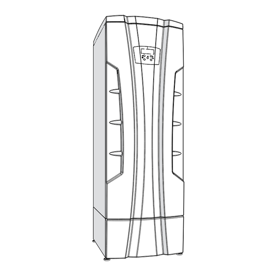
Aerco AM-R Series Installation And Maintenance Instructions Manual (136 pages)
Gas-fired condensing water heater
Brand:
Aerco
| Category:
Water Heater
| Size: 28 MB
Table of Contents
Safety Instructions
2
Table of Contents
8
1 Code Requirements
11
Regulations and Guidelines
11
Commonwealth of Massachusetts
12
2 General Information
13
Key to Symbols Used
13
Manufactured by
13
Description of Models
13
Accessories Included
13
3 Main Components
14
4 Function Overview
22
Intended Use and Functions
24
5 INSTALLATION - Location
25
Choosing the Installation Location
25
Prevent Combustion Air Contamination
29
Location of Water Heater
29
Residential Garage Installation
30
Closet and Alcove Installations
30
Clearances for Installation and Servicing
30
Clearances from Combustible Material
30
Vent and Combustion Air Piping
30
Prevent Combustion Air Contamination
30
6 INSTALLATION - Mounting the Heater
32
Transporting the Heater
32
Mounting the Heater
32
Dimensions
34
7 INSTALLATION - Water Side Head Loss of the Heater
35
8 INSTALLATION - Water Connections
36
Hot and Cold Water Piping
36
Near Water Heater Piping Components
36
Temperature and Pressure Relief Valve
37
Expansion Tank
38
Circulator Pump
38
Sizing Water System
38
Anti-Legionella
38
Low Water Cutoff Device
36
Water Heaters Water Connections
36
How to Install the Circulator Pump
38
Scalding
38
9 INSTALLATION - Condensate Disposal
41
Condensate Disposal
41
10 INSTALLATION - Electrical Connections
43
Electrical Connections: Overview
43
Connecting the Power Supply Cable
43
Connection to a LWCO Device
43
Alarm Contact
43
Connecting the Heater in Cascade
45
11 INSTALLATION - Removing of an Heater from a Common Venting System
46
Removing of an Heater from a Common Venting System
46
12 INSTALLATION - CATEGORY IV: Vent and Combustion Air
47
CATEGORY IV: Positive Pressure Condensing
47
CATEGORY IV: Venting and Air Piping Systems
47
Minimum / Maximum Allowable Combustion Air and Vent Piping Lengths
49
Install Vent and Combustion Air Piping
49
Air Inlet Pipe Materials
51
Sealing of PVC, CPVC or ABS Air Inlet Pipe
51
PVC/CPVC Vent Piping Materials
52
Installing PVC/CPVC Vent and Air Piping
52
PVC/CPVC Air Intake Connection
53
PVC/CPVC Vent Connection
53
Stainless Steel Vent Piping Materials
54
Stainless Steel Air Intake Connection
54
Stainless Steel Vent Connection
55
Polypropylene Vent Piping Materials
56
Polypropylene Air Intake Connection
57
Polypropylene Vent Connection
57
Single Pipe Vent (Not Sealed Combustion)
58
Determine Location
59
Sidewall Termination - Two Pipes
60
Vent/Air Termination
60
Determine Location
60
Prepare Wall Penetrations
62
Termination and Fittings
62
Multiple Vent/Air Terminations
62
Sidewall Termination - Concentric Vent
63
Description and Usage
63
Sidewall Termination Installation
63
Termination Clearances
63
Multiventing Sidewall Terminations
64
Vertical Termination - Two Pipes
65
Determine Location
65
Prepare Roof Penetrations
65
Termination and Fittings
65
Multiple Vent/Air Terminations
66
Vertical Termination - Concentric Vent
67
Description and Usage
67
Determine Location
67
Vertical Termination Installation
67
Multiventing Vertical Terminations
68
13 INSTALLATION - CATEGORY II: Vent and Combustion Air
69
CATEGORY II: Negative Pressure Condensing
69
CATEGORY II: Adapter and Increaser
69
Condensing Vent Option: CATEGORY II
70
14 INSTALLATION - Gas Supply
72
Gas Supply Piping
72
Pipe Sizing for Natural Gas
73
Propane Gas
73
Check Inlet Gas Supply Pressure
74
Operating at High Altitudes
74
Convert a Heater Model 199 or 250 from Natural Gas to Propane Gas or Viceversa
75
Gas Valve
75
Convert a Heater Model 399 or 500 from Natural Gas to Propane Gas or Viceversa
77
15 Start-Up
78
Operating
78
User Instructions
78
Filling the Condensate and Neutralizing Box
78
General Warnings Concerning Gas Supply
78
Confirming the Heater's Gas Type
79
Gas Type Conversion
79
Start-Up
79
Ignition Control Testing
79
Natural Gas
79
Gas Supply Pressure Checking
80
Checking and Adjusting CO2 Levels
81
Checking CO2 Level on Units Model 199 and 250
81
Checking CO2 Level on Units Model 399 and 500
81
Check the Capacity Input
82
Minimum Water Flow
82
16 Use
83
Check Water Pressure
84
Overview
84
Displays
84
Start-Up Procedure
84
Supply Water Temperature Adjustment
84
Water Temperature
84
Delays, Alarms and Protective Actions
85
Circulator Pump Protection
85
Heater's Freeze Protection
85
Display in Energy Saver Mode
85
Users' Menu
86
Installer's Menu
87
Diagnostic
88
Diagnostic: Lockouts "Loc
89
Diagnostic: Blocking Errors "Err
91
Flue Blocked Pressure Switch
92
Shuts Heater down
92
How to Clean the Appliance Jacket
92
17 Maintenance
93
Care and Maintenance
93
Address Reported Problems
94
Check All Piping for Gas Leaks
94
Verify Flue and Air Lines in Good Condition and Sealed Tight
94
Check System Water Pressure/System Piping/Expansion Tank
94
Check Control Settings
94
Check Ignition and Flame Sense Electrodes
95
Check Wiring and Connections
95
Perform Performance Verification
95
Flame Inspection
95
Check Flame Signal
95
Check Relief Valve
95
Check Heater Area
96
Check Pressure Gauge
96
Check Vent Piping
96
Check Air Piping
96
Check Condensate Drain System
96
Check Heater Piping (Gas and Water)
96
Shut Heater down
97
Test Low Water Cutoff (if Installed)
97
Reset Button (Low Water Cutoff)
97
Check Electronic Anode
97
Removing the Casing
98
Cleaning the Burner and Primary Heat Exchanger, Flue Gas Side
99
Thermal Insulations
102
Correct Positioning of the Ignition and Flame Detection Electrodes
103
Clean the Air Filter
103
Condensate Trap and Neutralizing Box Maintenance and Cleaning
104
Connection of the Display to Other Burners
105
How to Move a Control Board
106
Draining the Water from the Heater
107
Water and Flue Temperature Sensor
107
199 And 250 Models Wiring Diagram
108
399 And 500 Models Wiring Diagram
110
18 Technical Data
114
19 Spare Parts
116
20 Read out Flow Chart
131
21 Factory Menu
132
22 SEQUENCE of OPERATION for WATER HEATER
134
Advertisement
Advertisement
Related Products
Aerco AM 399B
Aerco AM 1000B
Aerco AM 399W
Aerco AM 500W
Aerco AM 1000W
Aerco AM Series
Aerco AM 500
Aerco AM 1000
Aerco AM 750
Aerco AM 750W
Aerco Categories
Boiler
Water Heater
Heater
Controller
Tools
More Aerco Manuals
Login
Sign In
OR
Sign in with Facebook
Sign in with Google
Upload manual
Upload from disk
Upload from URL