Aerco Esteem 399 Installation And Maintenance Manual
Low nox gas fired boiler
Hide thumbs
Also See for Esteem 399:
- Installation, operation & maintenance manual (188 pages) ,
- Installation supplement manual (30 pages) ,
- User manual (22 pages)
Table of Contents
Advertisement
Quick Links
Advertisement
Table of Contents

Related Manuals for Aerco Esteem 399


Summary of Contents for Aerco Esteem 399
- Page 1 OMM-0048_0A Instruction GF-125 AERCO INTERNATIONAL, Inc. Northvale, New Jersey, 07647 USA Installation and Maintenance Manual Esteem 399 Low NOx Gas Fired Boiler Visit www.aerco.com to View the Latest Product Manuals and Information. Printed in U.S.A. REVISED MAY 2010...
- Page 2 The information contained in this document is subject to change without notice from AERCO International, Inc. AERCO makes no warranty of any kind with respect to this material, including but not limited to implied warranties of mer- AERCO International, Inc.
-
Page 3: Table Of Contents
Esteem 399 Low NOx Installation and Maintenance Manual GF-125 Contents Chapter 1 Warnings and Cautions Emergency Shutdown ........... . . 2 Prolonged Shutdown . - Page 4 Domestic Hot Water System Piping......... . 19 System Piping - Zone Circulators .
- Page 5 If Esteem 399 Low NOx Does Not Start Correctly ......42...
- Page 6 Chapter 17 Maintenance Schedule Professional Maintenance ..........62 Owner Maintenance .
-
Page 7: Warnings And Cautions
Chapter 1 Warnings and Cautions Installers and operating personnel AUTIONS MUST, at all times, observe all safety Must be observed to prevent damage or loss of operating effectiveness. regulations. OTICE The following general warnings and cautions must be given the same attention as specific Indicates special instructions on instal- precautions included in these instructions. -
Page 8: Emergency Shutdown
CAUTION! To shut Down the Unit Many soaps used for gas pipe leak test- Turn the service switch on the Esteem 399 ing are corrosive to metals. The piping Low NOx control panel to “OFF” must be rinsed thoroughly with clean... -
Page 9: If You Smell Gas
MANUAL GAS CONTROL VALVE EXTERNAL TO THE APPLIANCE backside of the control panel when inquiring about service or troubleshooting. WARNING AERCO International accepts no liability for DO NOT ADD COLD MAKE UP WATER WHEN THE any damage resulting from incorrect installa- BOILER IS HOT... -
Page 10: Pre-Installation Items
13. Ensure the area chosen for the installation of • The National Fuel Gas Code NFPA54/ the Esteem 399 Low NOx is free of any com- ANSI Z 223.1 - Latest edition. bustible materials, gasoline and other flam- •... -
Page 11: Boiler Replacement
Boiler Replacement Boiler Replacement If the Esteem 399 Low NOx is replacing an existing boiler, the following items should be checked and corrected prior to installation: • Boiler piping leaks and corrosion. • Improper location and sizing of the expansion tank on the boiler heating loop. -
Page 12: Residential Garage Installations
See Chapter 10 for antifreeze LATEST EDITION guides. Residential Garage Installations When installing the Esteem 399 Low NOx in a residential garage, the following special precautions per NFPA 54/ANSI Z223.1 must be taken: • Mount the unit a minimum 18 inches [458 mm] above the floor level of the garage. -
Page 13: Combustion Air And Venting
Chapter 3 Combustion Air and Venting Combustion Air Contamination Potential contaminating products • Spray cans containing chloro/ uorocar- WARNING bons • Permanent Wave Solutions 399 L F THE STEEM X COMBUSTION • Chlorinated wax AIR INLET IS LOCATED IN ANY AREA LIKELY TO •... -
Page 14: Ventilation And Combustion Air Requirements - Direct Vent
Requirements - Category IV For Direct Vent installations, involving only the A Category IV appliance uses uncontaminated Esteem 399 Low NOx , in which the minimum indoor or outdoor air (surrounding the appli- service clearances are maintained as listed on ance) for combustion. -
Page 15: Indoor Combustion Air
Ventilation and Combustion Air Requirements - Category IV Methods of Supplying Combustion Air to one opening shall commence within 12 inches of the bottom of the enclosure. a Confined Space - Category IV The minimum dimension of air openings NDOOR OMBUSTION shall be not less than 3 inches. - Page 16 Ventilation and Combustion Air Requirements - Category IV Figure 3: : Figure 4: : All Combustion Air from Outdoors Through One All Combustion Air from Outdoors Through Permanent Air Opening Ventilated Attic • 1 sq. in./3000 Btu/hr of the total input •...
-
Page 17: Combination Of Indoor And Outdoor Combustion Air
Combustion Air and Vent Piping The Esteem 399 Low NOx is certified per OMBINATION OF NDOOR AND UTDOOR ANSI Z21.13 as a Category IV or Direct Vent OMBUSTION (sealed combustion) appliance. A Category Indoor Openings: Where used, openings con- IV appliance utilizes uncontaminated indoor... - Page 18 Removal of an Existing Boiler from a Common Vent System mon venting system placed in operation, while • Test for spillage at the draft hood relief the other appliances remaining connected to opening after 5 minutes of main burner op- the common venting system are not in opera- eration.
-
Page 19: Commonwealth Of Massachusetts Installations Only
Commonwealth of Massachusetts Installations Only For direct-vent appliances, mechanical-vent location of vent terminal. The plate shall heating appliances or domestic hot water be of sufficient size to be easily read equipment, where the bottom of the vent ter- from a distance of eight feet away, and minal and the air intake is installed below four read “Gas Vent Directly Below”. -
Page 20: Unit Preparations
OR CAUSE BODILY INJURY WHILE LIFTING OR mounted using the bracket provided with MOUNTING THE BOILER ONTO THE BRACKET the boiler. The Esteem 399 Low NOx is not NCE MOUNTED VERIFY THAT THE BOILER IS designed for floor installation. If floor installa-... -
Page 21: Boiler Mounting
Boiler Mounting Boiler Mounting • Locate the general area of the boiler place- ment. • Obtain assistance in lifting the boiler onto • Place the wall-mounting bracket on the the wall bracket. wall ensuring the upper edge of the brack- •... -
Page 22: Boiler Piping
Pressure Relief Valve Low Water Cutoff Device WARNING! • The Esteem 399 Low NOx is equipped with a factory installed pressure switch type Low AILURE TO COMPLY WITH THE GUIDELINES ON Water Cut Off device. -
Page 23: Additional Limit Control
Backfl ow Preventer • Wiring of the LWCO device to the • Use a backflow preventer valve in the Esteem 399 Low NOx is done directly make-up water supply to the unit as onto the 24V terminal strip, see Figure required by local codes. -
Page 24: Expansion Tank And Makeup Water
Ensure the expansion tank is properly sized for the boiler volume 7 gallons [26 L] for AUTION Esteem 399 Low NOx and the system volume DO NOT install automatic air vents on and temperature. a closed-type expansion tank system. -
Page 25: Domestic Hot Water System Piping
Figure 13, page 24 illustrates a single zone utilizing System Piping - Zone Circulators the boiler circulator as the system circulator. Connect the Esteem 399 Low NOx to the sys- System Piping - Radiant Heating tem piping as shown in Figure 10 page 23 when zoning with zone circulators. -
Page 26: System Piping - Special Application
System Piping - Special Application System Piping - Special Application System Piping - Multiple Units Installation If the boiler is used in conjunction with a chilled water/medium system, the boiler and Use a balanced manifold system as the pri- chiller must be piped in parallel. Install flow/ mary / secondary connection to the space check valves to prevent the chilled medium heating piping as shown in Figure 15 page 26. - Page 27 System Piping - Special Application Figure 7: Near Boiler Piping - Diaphragm Expansion Tank Note: Pitch horizontal piping upwards (1” of pitch per 5 ft of piping) towards expansion tank. Figure 8: Near Boiler Piping - Closed Type Expansion Tank System circulator Drain/purge valve Automatic air vent...
- Page 28 System Piping - Special Application Figure 9: DHW Boiler Piping with an Esteem 399 Low NOx Esteem 399 Low NOx boiler Flow/check valve water heater Pressure relief valve Isolation valve Drain/purge valve DHW circulator CH circulator OTICE The boiler system piping shown in Figure 8 must be a “closed”...
- Page 29 System Piping - Special Application CH System Piping - Zoning with Figure 10: Zone Circulators Esteem 399 Low NOx boiler Pressure relief valve CH circulator Air separator Flow/check valve Automatic air vent Isolation valve Diaphragm expansion tank Zone circulator Automatic fill valve...
- Page 30 Figure 12: CH System Piping - Multiple Zone Valve with Single System/Boiler Circulator Esteem 399 Low NOx boiler Air separator CH circulator Automatic air vent Isolation valve Diaphragm expansion tank...
- Page 31 • Note: Manifold mounted valve actuators may be used in lieu of zone valves. Figure 14: CH System Piping - Radiant/Low Temp. Heating Esteem 399 Low NOx boiler Air separator CH circulator Automatic air vent Flow check valve Diaphragm expansion tank...
- Page 32 GF-125...
-
Page 33: Chapter 6 Installing Vent, Air Intake & Drain
THE BALL IS LOST OR MISSING REPLACE THE condensate spillage. ENTIRE ASSEMBLY 3. Remove the compression nut and rubber 8. The Esteem 399 Low NOx will typically seal from the drain outlet. produce a condensate that is considered GF-125... - Page 34 slightly acidic with a pH content below 3.0. Install a neutralizing filter if required by authority having jurisdiction. AUTION The condensate drain must remain lled and unobstructed and allow un- restricted ow of condensate. The con- densate should not be subject to condi- tions where freezing could occur.
-
Page 35: Gas Piping
3. Install a sediment trap (drip leg) on the LINE COMPONENTS gas supply line prior to connecting to the Esteem 399 Low NOx gas train as shown in Figure 17. 4. Support the gas piping using hangers. Do not support the piping by the unit or its components. -
Page 36: Natural Gas
Refer to Table 1 for schedule 40 metallic pipe up pressure regulator for 13”w.c maximum. length and diameter requirements for natural WARNING! gas, based on rated Esteem 399 Low NOx input (divide by 1,000 to obtain cubic feet per DO NOT ADJUST OR ATTEMPT TO MEASURE hour). -
Page 37: Propane Gas
Propane Gas Propane Gas • Piping before and after the regulator should be straight rigid pipe for a minimum OTICE of 10 pipe diameters. The propane ori ce required for the Es- • Avoid exible pipe between boiler and the teem 399 Low NOx is 0.264”... -
Page 38: Pipe Sizing - Propane Gas
IZING ROPANE Contact the local propane gas supplier for rec- ommended sizing of piping, tanks and 100% lockup gas regulator. ROPANE UPPLY RESSURE EQUIREMENTS • Adjust the propane supply regulator pro- vided by the gas supplier for 13”w.c. maxi- mum pressure •... -
Page 39: Internal Wiring
ER SUPPLY TO THE UNIT BEFORE SERVICING Wiring Tool Instructions OR MAKING ANY ELECTRICAL CONNECTIONS 1. Locate the wiring tools on the Esteem 399 TO AVOID POSSIBLE ELECTRIC SHOCK HAZARD Low NOx just below the MCBA control in AILURE TO DO SO CAN CAUSE SEVERE PER a plastic bag and below the extra fuses. -
Page 40: Internal Wiring Diagram
Internal Wiring Diagram Figure 20: Esteem 399 Low NOx Boiler Factory Wiring GF-125... -
Page 41: External Wiring
OTICE amp (minimum) service switch. When making low voltage connections Domestic Hot Water Aquastat Wiring to the Esteem 399 Low NOx, ensure no external voltage is present in the ther- OTICE mostat circuits. If external voltage is Use only AERCO International supplied present, provide an isolated contact to aquastat (P/N 69107). -
Page 42: Ch And Dhw Circulator
1. Connect the space heating primary circu- Outdoor Reset Control lator to the Esteem 399 Low NOx 120 V The Esteem 399 Low NOx may operate with terminals 1,2 and 3 as shown in Figure a variable boiler operating temperature using 20, page 34. -
Page 43: External Wiring Diagram
External Wiring Diagram External Wiring Diagram 4 Wire Zone Valve Figure 22: Field Wiring with Zone Circulators 3 Wire Zone Valve Figure 23: Multiple Zone Field Wiring Using Zone Valves GF-125... - Page 44 Figure 24: Field Wiring with Zone Circulators Figure 25: Typical Zone Relay Panel Wiring GF-125...
-
Page 45: Start-Up Preparation
WARNING! HLORINATED ATER NEVER Do not use the Esteem 399 Low NOx to heat USE AUTOMOTIVE OR ETHYLENE GLY COL ANTIFREEZE OR UNDILUTED ANTIFREEZE IN a swimming pool or spa directly. THE PRIMARY SYSTEM AS FREEZE PROTECTION Maintain the chlorine level of the water at lev- HIS CAN CAUSE SEVERE PERSONAL INJURY els considered safe for drinking. -
Page 46: Filling The Boiler System
Check Low Water Cut-Off Device Ensure the concentration of antifreeze to • The Esteem 399 Low NOx is provided water does not exceed a 50/50 ratio. with a factory installed LWCO device that measures system pressure of more than OTICE 10 psi. -
Page 47: Check Thermostat Circuit
Use an isolation relay to prevent voltage from the external circuit entering the Esteem 399 Low NOx con- trol panel. 2. Reconnect the external thermostat wires to the 24V terminal strip on the wiring panel. -
Page 48: Start-Up Procedures
• if applicable, ensure the external limit is for proper propane gas orifice size: 6.7 reset to the closed position. mm for Esteem 399 Low NOx . Refer to • Ensure incoming gas supply pressure at Figure 18, page 31 for location of the pro- the unit is more than 5”w.c. -
Page 49: First Run Check Of The Unit And System
THE COMBUSTION LEVELS ARE NOT WITHIN THE Check Gas Piping RANGE GIVEN IN ABLE FOR THE FIRING RATE Check around the unit for gas odor fol- AERCO SHUT THE BOILER DOWN AND CONTACT lowing the procedure on page 40 of this NTERNATIONAL NGINEERING EPARTMENT manual. -
Page 50: Set Boiler Ch Set Point
The last three dig- 3. Turn off all gas appliances within the its on the display represent the meas- building, except the Esteem 399 Low NOx ured boiler water temperature and may differ from what is shown in the manual. - Page 51 Operation Veri cation - Domestic Hot Water • If the burner flame proves, the burner additional 30 seconds before starting a will continue to fire at the ignition fan new ignition sequence. speed for approximately 10 seconds to • [ ] The space heating circulator 7180 stabilize the flame.
-
Page 52: Operation Verification - Domestic Hot Water
Operation Verifi cation - Domestic 4. Verify the DHW operation of the boiler by repeating the outlined operation sequence Hot Water several times. 1. As outlined in the verification for space 5. Return the DHW aquastat and room ther- heating, repeat STEPS 2 through 4. mostat to the desired setting. -
Page 53: Operating Instructions
Chapter 12 Operating Instructions Safety FOR YOUR SAFETY READ COMPLETE INSTRUCTIONS BEFORE PROCEEDING WARNING F YOU DO NOT FOLLOW THESE INSTRUCTIONS EXACTLY A FIRE OR EXPLOSION MAY RE SULT CAUSING PROPERTY DAMAGE PERSONAL INJURY OR LOSS OF LIFE IF YOU SMELL GAS •... -
Page 54: Operation
TO TURN OFF GAS TO APPLIANCE 1. Set the room thermostat to lowest setting. 2. Turn the service switch on the Esteem 399 Low NOx control panel to “OFF” 3. Turn the external manual gas valve handle clockwise to “CLOSE”... -
Page 55: Boiler Control Display
StbY played. Then press and hold both MODE and This is the standard mode for the Esteem 399 Low NOx. The control automatically returns to this mode after 20 minutes if no keys have been pressed on the display. Any parameters that were modified are then stored. - Page 56 Operation Standby Mode Display GF-125...
-
Page 57: Parameter Mode-Setting The Boiler Parameters
Boiler Control Display —S Note 1: This parameter is factory set to 140ºF. ARAMETER MODE ETTING OILER It is important to note the control adds 46ºF to ARAMETERS this setting, therefore the actual domestic hot water boiler setpoint is 140ºF + 46ºF = 186ºF. To access PARAMETER mode when the sys- tem is in STANDBY mode, press the MODE button once. -
Page 58: Information Mode-Accessing Boiler Information
Boiler Control Display —A NFORMATION CCESSING OILER OTICE NFORMATION The ignition counters and burner hours are split into three two digit numbers. For example: switch from STANDBY mode INFORMATION mode, press MODE twice. Write the numbers down from left to right to arrive at 123,456 space heating ignitions. -
Page 59: Error (Hard Lockout) Mode
Boiler Control Display RROR OCKOUT If a serious fault occurs, the system enters a hard lockout condition which requires a manu- al reset by pressing the RESET button. A hard lock is indicated by displaying an E for the first digit, followed by the error code. -
Page 60: Outdoor Reset Control
Chapter 13 Outdoor Reset Control Mounting the Outdoor Sensor 8. Tap the enclosed plastic anchors into the pilot holes. Use care not to damage the 1. Remove the front cover, mounting screws anchors. & anchors from the sensor enclosure. 9. Mount the sensor enclosure using the 2. -
Page 61: Adjusting Outdoor Reset Curve
Adjusting Outdoor Reset Curve setpoint on the CH Reset Curve Coldest Day. AUTION The outdoor temperature can be monitored on If a parameter setting is changed but the the boiler display via item 4 of the INFO menu. STORE button is not pressed to save the setting, the MCBA will automatically CH M INIMUM... -
Page 62: Entering Mcba Access Code
Entering MCBA Access Code Entering MCBA Access Code After the Access Code has been entered, the advanced parameters can be accessed by The installer must enter the MCBA Access pressing the MODE button until the display Code to adjust the advanced parameter set- shows . - Page 63 Entering MCBA Access Code Graph 1: Outdoor Air Temperature Reset Curve (Example) Table 3: Outdoor Air Temperature Reset (Example) Boiler target Temp. Based on Outdoor Temperature Outdoor Temp. 0ºF or Lower 140ºF 23ºF 122ºF 40ºF 108ºF 64ºF or Higher 86ºF Graph 1 illustrates Parameter 4 adjusted to 140ºF target temperature at 0ºF outdoor air temperature Note: Factory setting of Parameter 4 is 186ºF.
-
Page 64: External Modulating Control
Reversed polarity could lead to erratic and/or no response from the boiler con- troller. Parameter Adjustment The Esteem 399 Low NOx MCBA control module must be programmed to accept the 0-10 VDC signal from the external modulating boiler control. CH Operating Signal Section... -
Page 65: Factory Parameter Settings
Factory Parameter Settings Factory Parameter Settings 140ºF DHW Setting DHW Application Selection CH Application Selection 186ºF CH Maximum Boiler Operating Setpoint 86ºF CH Minimum Boiler Operating Setpoint 00ºF CH Reset Curve Coldest Day 64ºF CH Reset Curve Warmest Day -22ºF Frost Protection Setpoint 32ºF CH Block Temperature Setting... -
Page 66: Chapter 15 Check-Out Procedures
Measured the rate of input on Natural Gas as outlined on page 44. Checked the incoming gas pressure to the Esteem 399 Low NOx to ensure a minimum pressure of 5”w.c during ow conditions to all gas appliances and a maximum pressure of 13”w.c during non-... -
Page 67: Chapter 16 Installation Record
Chapter 16 Installation Record GF-125... -
Page 68: Maintenance Schedule
Chapter 17 Maintenance Schedule Professional Maintenance Owner Maintenance • On going as conditions warrant: At least on an annual basis the following main- • Check the area around the unit. tenance should be performed by a qualified • Check and remove any blockage from the service technician: combustion air inlet and ventilation open- ings. -
Page 69: Maintenance Procedures
Chapter 18 Maintenance Procedures WARNING! Inspect Burner Area Remove the boiler front jacket panel and ven- 399 L STEEM X SHOULD BE IN turi inlet elbow. SPECTED AND SERVICED ANNUALLY PREFER ABLY AT THE START OF THE HEATING SEASON Vacuum any dirt or debris from the burner/ BY A QUALIFIED SERVICE TECHNICIAN N AD blower components. -
Page 70: Clean Condensate Drain Assembly
Clean Condensate Drain Assembly Clean Condensate Drain Assembly Inspect Vent and Combustion Air Piping 1. Loosen the retaining nut from the conden- sate drain assembly and disconnect the Visually inspect the venting system and com- assembly from the boiler. bustion air piping for blockage, deterioration or 2. -
Page 71: Check Expansion Tank
Check Expansion Tank Check Expansion Tank Check Boiler Relief Valve Refer to Section IV - Boiler Piping for recom- Inspect the relief valve and lift the lever to ver- mended location of the expansion tank and ify flow at least annually or as recommended air eliminators. -
Page 72: Check Ignition Wiring And Ground Wiring
Check Ignition Wiring and Ground Wiring Check Ignition Wiring and Ground Not damage combustion chamber insula- tion during removal of burner mounting Wiring plate assembly. See WARNING page 67. • Inspect the burner wiring from the burner 8. Remove the burner head mounting control module to the ground terminal be- screws and remove the burner head. -
Page 73: Check Flame Signal
Check Flame Signal Check Flame Signal Check Flue Gas Temperature 1. Adjust the boiler to fire at HIGH fire, see The flame signal can be read from item E of the page 49. Place the control display to INFO information mode. It should be a min. 3 mode, see page 52 for procedures. -
Page 74: Start-Up And Checkout Procedures
Clean Heat Exchanger Clean Heat Exchanger tion if necessary. See WARNING on page 1. Shut down the boiler: 12. Re-assemble the blower onto the burner • Turn Off Gas to Appliance. See instruc- mounting plate and reconnect the wiring tions on page 48 harness connectors. -
Page 75: Chapter 19 Troubleshooting
Introduction Chapter 19 Troubleshooting Introduction This guide is to be used in conjunction with the AERCO International Esteem 399 Low NOx Boiler Installation and Maintenance Manual. Good Troubleshooting Practices Before leaving for the job site: • Check your parts and tools •... -
Page 76: Control Module Fuses
Control Module Fuses Initial Troubleshooting Checks WARNING ABEL ALL WIRES AND WIRE CONNECTIONS PRIOR TO DISCONNECTING WHEN SERVICING ANY BOILER CON TROLS IRING ERRORS CAN CAUSE IMPROPER AND DANGEROUS OPERATION LWAYS DISCONNECT THE POWER SUPPLY TO THE BOILER BEFORE SERVICING AILURE TO COMPLY COULD RESULT IN SEVERE PER SONAL INJURY DEATH OR SUBSTANTIAL PROPERTY DAMAGE... - Page 77 8. Reconnect the external power supply to the boiler and perform the verification of operation steps as outline in the Esteem 399 Low NOx Installation Manual. WARNING FTER COMPLETING ANY SERVICING OF THE BOILER VERIFY PROPER OPERATION OF THE BOILER...
- Page 78 Boiler Control Module Display Messages Boiler Control Module Display Messages Display shows a number of 1 to 8 for the first digit on the left followed by 2 or 3 dig- its (boiler temperature) The boiler is in normal operating mode. Display is blank •...
- Page 79 Boiler Control Module Display Messages check the DHW thermostat wiring and thermostat control. Replace as needed. Remove jumper when completed. • Disconnect power to the boiler. Check all wiring and wiring connections and compare to the wiring diagram. Ensure all wiring and wiring connection are in good condition and secure. If necessary, replace complete wiring harness.
-
Page 91: Appendices
Appendices Appendix A: Replacement Parts Figure 28: Esteem 399 Low NOx Jacket Components Item Part # Description 38027 Display Control Panel 38028 (Left) Display Control Panel Extensions (Not Shown) 38029 (Right) 34028 Base Panel 37051 Front Jacket Panel 37052 Side Jacket Panel (Left and Right) -
Page 92: Insulation Handling
Figure 29: Esteem 399 Low NOx Internal Components Item Part # Description 28191 Heat Exchanger Body 38030 Vent Outlet Adapter 38031 Combustion Air Inlet Adapter 61022 Supply & Return NTC Sensor (NTC1, NTC2) 61023 Flue NTC Sensor (NTC5) 60013 LWCO Pressure Device... - Page 93 Figure 30: Esteem 399 Low NOx Burner Components Item Part # Description 83025 Combustion Chamber Insulation 24230 Burner Head with Gasket 36059 Burner Plate 58026 Blower with Gasket 92078 Gas Valve Venturi 63086 Ignition Cable 58027 Igniter with Gasket 58028...
-
Page 94: Appendix B: Unit Specifications
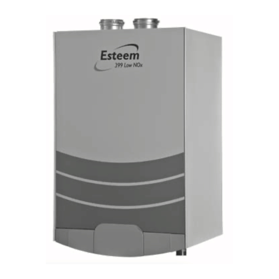
Esteem 399 Low NOx output rating is based on the thermal efficiency. Input and output ratings are shown for sea level applications. The Esteem 399 Low NOx automatically derates the input at approximately 2% for every 1,000 Ft. of altitude. No alterations to the boiler or burner system is required. - Page 95 Appendix B: Unit Speci cations Figure 32: Front View Esteem 399 Low NOx GF-125...
- Page 96 Appendix B: Unit Specifications Figure 33: Side View Esteem 399 Low NOx GF-125...
-
Page 97: Appendix C: Pressure Drop Comparison Tables
Appendix C: Pressure Drop Comparison Tables Appendix C: Pressure Drop Comparison Tables Graph 3: Pressure Loss Through Boiler - Grundfos Circulators Graph 2: Pressure Loss Through Boiler - Taco Circulators • Note: Minimum allowable ow rate at full input: 19 gpm GF-125...
Need help?
Do you have a question about the Esteem 399 and is the answer not in the manual?
Questions and answers