
Related Manuals for Trikdis GV17


Summary of Contents for Trikdis GV17
- Page 1 GSM gate controller GV17 Installation manual November 2018 www.trikdis.com UAB Trikdis Draugystės str. 17, LT-51229 Kaunas, Lithuania +370 37 408 040 info@trikdis.lt...
-
Page 2: Table Of Contents
........................ 6 INDICATION OF OPERATION 1.5 GSM GV17 ................7 GATE CONTROLLER STANDARD PACKING LIST 2 WIRING SCHEMATICS FOR THE GSM GATE CONTROLLER GV17 ............7 2.1 F ............................7 ASTENING 2.2 S ..................8 CHEMATIC FOR CONNECTING THE POWER SUPPLY 2.3 S... -
Page 3: Safety Precautions
GSM gate controller GV17 Safety precautions The GSM gate controller should only be installed and maintained by qualified personnel. Please read this manual carefully prior to installation in order to avoid mistakes that can lead to malfunction or even damage to the equipment. -
Page 4: Description
7 administrator and 990 user telephone numbers. A user control schedule and counter for how many times a specific user can control the system can be set for the GV17. The GSM controller can send SMS messages informing when inputs and outputs are activated and restored (the text of the SMS messages is customizable). -
Page 5: Specifications
GSM gate controller GV17 1.1 Specifications Parameter Description 2G GSM modem frequencies 850 / 900 / 1800 / 1900 MHz 3G UMTS modem frequencies 800 / 850 / 900 / 1900 / 2100 MHz Power supply voltage 9-32 V DC... -
Page 6: Purpose Of Terminals
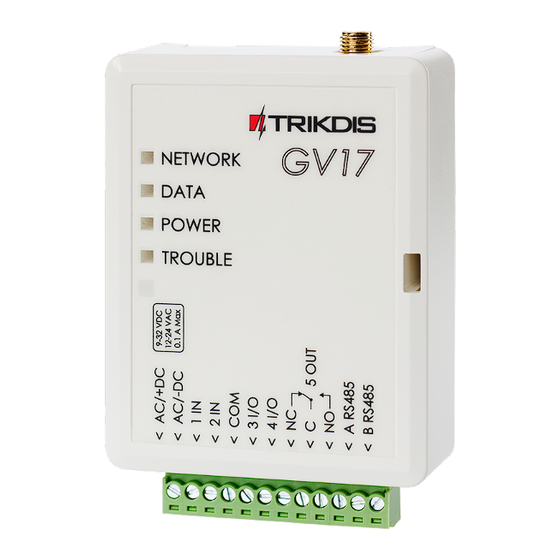
GSM gate controller GV17 1.3 Purpose of terminals Terminal Description AC/+DC Power terminal (9-32 V DC positive; 12-24 V AC) AC/-DC Power terminal (9-32 V DC negative; 12-24 V AC) 1 IN input, of selectable type NO, NC, EOL (factory setting: NO) -
Page 7: Gsm Gate Controller Gv17 Standard Packing List
Double-sided adhesive tape (5 cm) 1 pc. Screw 2 pcs. 2 Wiring schematics for the GSM gate controller GV17 2.1 Fastening 1. Remove the top lid. Pull out the plug part of the terminal block. 2. Remove the PCB board. -
Page 8: Schematic For Connecting The Power Supply
2.3 Schematics for connecting inputs The GV17 has four inputs IN (two of which are universal and can operate either as inputs or outputs) for the connection of various alarm sensors. These inputs can operate in NC, NO, EOL modes. Connect the inputs according to the set input type (NC, NO, EOL) as is shown in the schematics bellow: 2.4 Schematic for connecting the relay... -
Page 9: Quick Set Up Of The Controller
SIM card number will turn on the 5 OUT relay output for 3 (three) seconds. The controller can be installed without any additional configuration if such operation mode is acceptable. 1. A nano-SIM card must be inserted into the GV17. Turn off PIN code requests for the card before inserting it into the controller. -
Page 10: Control Using Protegus Cloud
4.3 Control using Protegus cloud With Protegus users will be able to control GV17 remotely. They will also be able to see the system state and receive all system event messages. 1. Download and launch the Protegus app or use the browser version of Protegus at www.protegus.eu/login. - Page 11 Level or Pulse output operation mode. 6. After clicking on a PGM button, the GV17 output is turned on. (Example: PGM3 – output turned off; PGM4 – output turned on, the PGM operation mode Level is set; PGM5 – output turned on, the PGM operation mode Pulse is set) www.trikdis.com...
-
Page 12: Control With Sms Messages
GSM gate controller GV17 4.4 Control with SMS messages Control the relay output OUT5 with these SMS commands: OUTPUT5 xxxxxx ON OUTPUT5 xxxxxx OFF OUTPUT5 xxxxxx PULSE=002 xxxxxx 6-symbol administrator password. (default code – 123456). Turn on output. Turn off output. -
Page 13: Configuration With Sms Messages
NAME User’s name or e-mail. Once the first number is added to the GV17’s user phone list, the controller will react only to phone calls from the numbers on the list. The controller will ignore calls from other numbers. 3. Give administrator rights to another user You can give administrator rights to other people. -
Page 14: November
GSM gate controller GV17 Command Data Description SETU phonenr#name Add new user. Adds the phone number and name to the list. The number must be separated from the name with a hash (#). The number must start with + and the international code. -
Page 15: Setting Parameters Using Trikdisconfig Software
4. Launch the configuration software TrikdisConfig. The program will automatically recognize the connected device and will automatically open the GV17 configuration window. 5. Click Read [F4] to see current GV17 parameters. If prompted, enter administrator’s or installer’s code in the pop-up window. -
Page 16: Trikdisconfig Status Bar
GSM gate controller GV17 5.1 TrikdisConfig status bar After connecting the GV17 to the TrikdisConfig software, the software will show information about the connected device in the status bar: Name Description IMEI/Unique ID The device’s IMEI number State Operational state... -
Page 17: In/Out" Window
GSM gate controller GV17 Settings group “General” Object ID – enter account number (4 symbol hexadecimal number, 0-9, A-F), provided by the alarm receiving center. Object name – every event will be sent with the object name. Time synchronization – choose a source for setting the time. -
Page 18: Ip Reporting" Window
GSM gate controller GV17 Pulse time – time for which the output is turned on, when output is set as Pulse type. Sched – assign a schedule number for controlling the output. Assign IN – assign input (IN) to output to see the actual state of the device depending on the input’s state. -
Page 19: User List" Window
This channel works only when GPRS mode is set both for the main channel and backup channel. SMS messages will be sent to the response center’s SMS receiver: 1) as soon as the GV17 is enabled for the first time; 2) after loss of TCP/IP or UDP/IP connection in the main and backup channels. - Page 20 GSM gate controller GV17 Name/E-mail – specify administrator’s name or e-mail address. Tel number – specify administrator’s phone number (e.g.: +370xxxxxxxx). Control – specify the outputs that the administrator will control. SMS notification – specify events (IN1, IN2, OUT3, OUT4, OUT5) that the administrator will receive SMS notifications about.
-
Page 21: Events Log" Window
GSM gate controller GV17 “Scheduler” tab Enable – enable time schedule when the user will be able to control the controller’s outputs. Start time – specify time and days of the week from when the user can control controller’s outputs. -
Page 22: Restore Default Settings
3. Launch the configuration program TrikdisConfig and in the field Unique ID of the Remote access section enter the IMEI number of your GV17 (the IMEI number is given on the stickers that can be found on the lower part of the device’s case and on the packaging). -
Page 23: Updating Firmware Manually
1. Launch TrikdisConfig. 2. Connect the GV17 to a computer using a USB Mini-B cable or connect to the GV17 remotely. If a newer version of firmware is available, the program will offer to install it. 3. Choose the menu branch Firmware.
Need help?
Do you have a question about the GV17 and is the answer not in the manual?
Questions and answers