Table of Contents
Advertisement
Please read this document carefully before using this product. The guarantee will be invalidated if the device is damaged by not following instructions
detailed in the manual. The company shall not be responsible for any damage or losses however caused, which may be experienced as a result of the
installation or use of this product.
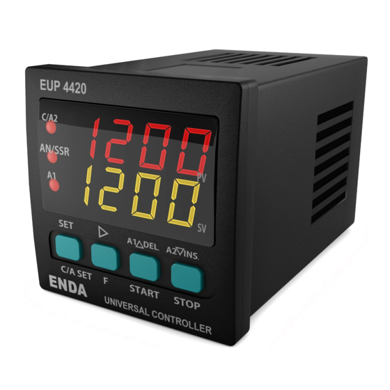
ENDA EUP SERIES PID UNIVERSAL CONTROLLER
Thank you for choosing ENDA EUP Series Universal Controller Devices.
Dual setpoint value can be selected.
PT100 ,J, K, L, T, S, R sensor (thermocouple) types can be selected.
0-20mA, 4-20mA, 0-10V, 2-10V, 0-25mV and 0-50mV input selections.
Auto calculation for PID parameters (SELF TUNE).
Self tune for automatic PID calculation or
manually enter PID parameters if known.
Three different feature can be assigned to digital input.
Three different feature can be assigned to F function key.
Soft-Start feature.
Analogue, SSR or Relay Output Control selection.
0-20mA and 4-20mA Analogue Output Control selection.
Up to 16 steps Profile Control.
A1 Relay output programmable as first Alarm or Cooling control output.
C/A2 Relay output can be used as second Alarm or Temperature Control output.
Heating/Cooling control selection.
Zero point input shift.
In case of sensor failure, periodically, auto-periodically running or relay state can be selected.
RS485 Modbus RTU communication protocol feature (Specify at order).
CE marked according to European Norms.
Order Code : EUP
4
2 0
1
1 - Size
2 -
Supply Voltage
4420.....48x48x87mm
230VAC...90 - 250V AC
7420.....72x72x97mm
SM...........9-30V DC /
8420.....48x96x87mm
7-24V AC
9420.....96x96x50mm
Input Type
PT100 Resistance Thermometer
PT100 Resistance Thermometer
J (Fe-CuNi)
Thermocouple
J (Fe-CuNi)
Thermocouple
K (NiCr-Ni)
Thermocouple
K (NiCr-Ni)
Thermocouple
L (Fe-CuNi)
Thermocouple
L (Fe-CuNi)
Thermocouple
T (Cu-CuNi)
Thermocouple
T (Cu-CuNi)
Thermocouple
S (Pt10Rh-Pt) Thermocouple
R (Pt13Rh-Pt) Thermocouple
0-20mA input
4-20mA input
0-10V input
2-10V input
0-25mV input
0-50mV input
ENVIRONMENTAL CONDITIONS
Ambient/storage temperature
0 ... +50°C/-25 ... +70°C
Max. Relative humidity
Relative humidity 80% for temperatures up to 31°C decreasing linearly to 50% relative humidity at 40°C.
Rated pollution degree
According to EN 60529;
Height
Max. 2000m
KEEP AWAY device from exposed to corrosive, volatile and flammable gases or liquids and DO NOT USE the device in similar hazardous locations.
ELECTRICAL CHARACTERISTICS
Supply
90-250V AC, 50/60Hz or 9-30VDC / 7-24VAC ±%10 SMPS
Power consumption
Max. 5VA
Wiring
Power screw-terminal connections: 2.5mm²', Signal screw-terminal connections: 1,5mm².
Line resistance
Max. 100 Ohm
Data retention
EEPROM (minimum 10 years)
EMC
EN 61326-1: 2013 (Performance criterion B satisfied for EN 61000-4-3 standard).
Safety requirements
EN 61010-1: 2010 (Pollution degree 2, overvoltage category II)
OUTPUTS
C/A2 Output
Relay : 250V AC, 8A (for resistive load), NO+NC (Control or Alarm2 Output selection).
Relay : 250V AC, 8A (for resistive load), NO (Alarm1 and Cooling Control Output selection).
A1 Output
ANL/SSR Output
Max. SSR Output ; 0-20mA, 4-20mA, 24V 20mA. Max. load resistance ; 600 Ohm (12 bit 0.2% accuracy).
Life expectancy for relay
Without load 30.000.000 switching; 250V AC, 8A (resistive load) 300.000 switching.
CONTROL
Single Setpoint and Alarm Control.
Control type
Control algorithm
On-Off / P, PI, PD, PID (selection).
14 bit.
A/D converter
Min. 100ms.
Sampling time
Can be adjusted between %0.0 and %100.0 . If Pb=%0.0 , ON-OFF control is selected.
Proportional band
Can be adjusted between 1 and 125secs.
Control period
Can be adjusted between 1 and 50°C/F.
Hysteresis
Setpoint value ratio can be adjusted between %0 and %100 .
Output power
HOUSING
Housing type
Suitable for flush-panel mounting according to DIN 43 700.
EUP4420 : W48xH48xD87mm, EUP7420 : W72xH72xD97mm,
EUP8420 : W48xH96xD87mm, EUP9420 : W96xH96xD50mm.
Weight
Approx. 400g (250g for EUP4400) After packing.
Self extinguishing plastics
Enclosure material
Avoid any liquid contact when the device is switched on.
DO NOT clean the device with solvent (thinner, gasoline, acid etc.) and / or abrasive cleaning agents.
SİSEL MÜHENDİSLİK ELEKTRONİK SAN. VE TİC. A.Ş.
Şerifali Mah.
Barbaros Cad. No:18
ÜMRANİYE/İSTANBUL-TURKEY
Tel : +90 216 499 46 64 Pbx.
url : www.enda.com.tr
2
3
3 -
Modbus (Optional)
RS........ RS-485
Modbus Available
(Optional / Specify at order).
Blank....
N/A
Please see EUPx420 Series Modbus
Address Map and Connection Diagram
Guide for Modbus feature.
Scale Range
°C
-199.9...600.0
EN 60751
°C
-200...600
°C
EN 60751
-30.0....600.0°C
EN 60584
-30....600°C
EN 60584
EN 60584
-30.0...999.9°C
EN 60584
-30...1300°C
-30.0....600.0°C
DIN 43710
DIN 43710
-30....600°C
EN 60584
-30.0...400.0°C
EN 60584
-30....400°C
EN 60584
-40...1700°C
-40...1700°C
EN 60584
-1999...+9999 (max. scale range 10000)
-1999...+9999 (max. scale range 10000)
-1999...+9999 (max. scale range 10000)
-1999...+9999 (max. scale range 10000)
-1999...+9999 (max. scale range 10000)
-1999...+9999 (max. scale range 10000)
Front panel
Y.Dudullu 34775
Fax : +90 216 365 74 01
°F
-199.9...999.9
°F
-328....1112
°F
-22.0....999.9 °F
-22....1112 °F
-22.0....999.9 °F
-22....2372 °F
-22.0....999.9 °F
-22....1112 °F
-22.0....752.0 °F
-22......752
°F
-40....3092
°F
-40....3092
°F
:
IP65,
Rear panel :
IP20
1/6
EUP7420
EUP4420
C/A2
1200
SSR
PV
A1
1200
SV
SET
A1
DEL.
A2
INS.
C/A SET
F
STOP
C/A SET
START
ENDA
ENDA
UNIVERSAL CONTROLLER
EUP8420
ENDA
PV
C/A2
SV
SSR
A1
A1
SSR
C/A2
SET
SET
A1
DEL. A2
INS.
C/A SET
C/A SET
F
START
STOP
ENDA
UNIVERSAL CONTROLLER
Accuracy
0,2% (
for full scale
)
1 digit
0,2% (
for full scale
)
1 digit
0,5% (for full scale)
1 digit
0,5% (for full scale)
1 digit
0,5% (for full scale)
1 digit
0,5% (for full scale)
1 digit
0,5% (for full scale)
1 digit
0,5% (for full scale)
1 digit
0,5% (for full scale)
1 digit
0,5% (for full scale)
1 digit
0,5% (for full scale)
1 digit
0,5% (for full scale)
1 digit
0,2% (
for full scale
)
1 digit
0,2% (
for full scale
)
1 digit
0,2% (
for full scale
)
1 digit
0,2% (
for full scale
)
1 digit
0,2% (
for full scale
)
1 digit
0,2% (
for full scale
)
1 digit
PV
SV
C/A2
SSR
A1
A1
DEL. A2
INS.
SET
F
START
STOP
UNIVERSAL CONTROLLER
EUP9420
PV
SV
UNIVERSAL CONTROLLER
A1
DEL.
A2
INS.
F
START
STOP
ENDA
TM
EUPx420-EN-01-181112
Advertisement
Table of Contents

Related Manuals for sisel ENDA EUP Series


Summary of Contents for sisel ENDA EUP Series
- Page 1 The company shall not be responsible for any damage or losses however caused, which may be experienced as a result of the installation or use of this product. ENDA EUP SERIES PID UNIVERSAL CONTROLLER Thank you for choosing ENDA EUP Series Universal Controller Devices. Dual setpoint value can be selected. EUP7420 PT100 ,J, K, L, T, S, R sensor (thermocouple) types can be selected.
- Page 2 RUNNING MODE ENTERING TO PROGRAMMING MODE During in "Programming Mode", if no key is pressed for 20 sec, settings automatically saved and device returns to the "Running Mode" (to the home screen). Alternatively, by pressing key "Running Mode" is entered and by pressing both keys at once, settings automatically saved and device returns to C/A SET key is pressed while holding...
- Page 3 TERMS SETTING OPTIONS IN RUNNING MODE SETTING UP ALARM CONTROL AND SETPOINT VALUES ( 1 ) Indicates measured value and set values in “Running Mode”. EUP4420 Indicates the parameters and names in “Programming Mode”. C/A2 ( 2 ) Lights up, if timer is displayed and flashes while timer is running.. 1200 if the P.
- Page 4 MOTORIZED VALVE CONNECTION AND SETTINGS Diagram-1 OPEN AC 250V 2A RESISTIVE LOAD C/A2 (VALVE OPEN) CLOSE A1 AC 250V 2A RESISTIVE LOAD (VALVE CLOSE) Motorized valve connection must be applied as shown figure above (if the motorized valve electrical values are incompatible with EUPx420 contact output values, an additional contactor must be connected).
- Page 5 MULTI-STEP PROFILE CONTROL OUTPUT GRAPHICS Diagram-5 Step1 Step2 Step3 Step4 Step5 Target Temperature tE. . 0 2 =100 tE. . 0 3 =300 tE. . 0 4 =300 tE. 0 1 =100 tE. . 0 5 =100 S. n um should be set to 5 Time ti.
- Page 6 DIMENSIONS Depth To removing the device from the panel: - While pressing both side of the device in direction , and push it in direction EUP4420 C/A2 1200 Connection Cables 1200 Flush mounting DEL. INS. clamp Panel C/A SET START STOP ENDA UNIVERSAL CONTROLLER...
- Page 7 ENDA EUPx420 SERIES PID TEMPERATURE CONTROLLER MODBUS PROTOCOL ADDRESS MAP 1.1 Memory Map for Holding Registers Holding Register Parameter Data Default Read / Write Parameter Data Content Adress Number Type Value Name Permission Decimal (Hex) Control output, temperature setpoint value C1.
- Page 8 ENDA EUPx420 SERIES PID TEMPERATURE CONTROLLER MODBUS PROTOCOL ADDRESS MAP 1.1 Memory Map for Holding Registers (continue) Holding Register Parameter Data Default Read / Write Parameter Data Content Adress Number Type Value Name Permission Decimal (Hex) Digital input control parameter ( 0 = Digital input off, 1 = 2nd set value can be selected by digital input, d.
- Page 9 ENDA EUPx420 SERIES PID TEMPERATURE CONTROLLER MODBUS PROTOCOL ADDRESS MAP 2.1 Memory Map for Profile Control Holding Registers Holding Register Data Default Parameter Read / Write Parameter Adress Data Content Type Number Value Name Permission Decimal (Hex) Word Profile time base set value. (0 = 0000s,1 = 00m59s, 2 = 0000m, 3 = 99m59s) t.
- Page 10 ENDA EUPx420 SERIES PID TEMPERATURE CONTROLLER MODBUS PROTOCOL ADDRESS MAP 2.2 Memory Map for Step Control Bits Data Parameter Read / Write Default Parameter Coil Address Data Content Type Number Permission Name Value 0100d (0064h) A1 alarm output programming coils in profile steps ; PC0-PC15 0115d (0073h) If PC0=1, A1 output is ON at 1st step..
- Page 11 ENDA EUPx420 SERIES PID TEMPERATURE CONTROLLER MODBUS PROTOCOL ADDRESS MAP 4. MODBUS ERROR MESSAGES Modbus protocol has two types error, communication error and operating error. Reason of the communication error is data corruption in transmission. Parity and CRC control should be done to prevent communication error. Receiver side checks parity and CRC of the data.
Need help?
Do you have a question about the ENDA EUP Series and is the answer not in the manual?
Questions and answers