Table of Contents
Advertisement
Advertisement
Table of Contents

Related Manuals for JAMAR Technologies RAC Plus Series


Summary of Contents for JAMAR Technologies RAC Plus Series
- Page 2 JAMAR factory or authorized service agent. In no event shall JAMAR Technologies, Inc. be liable for any damages arising from the use of this product including damages arising from the loss of information.
- Page 3 For more information on our products, or for the latest news in product development, visit our web site at: www.jamartech.com For support information specific to the RAC Plus devices, go to: www.jamartech.com/RACPlusSupport.htm Address any correspondence to: JAMAR Technologies, Inc. 151 Keith Valley Road Horsham, PA 19044-1411 Volume 1.2 May 2006...
-
Page 4: Table Of Contents
RAC Plus User’s Manual Table of Contents Technical Support ............iii Introduction to the RAC Plus I and Plus II........1-1 What are the RAC Plus I and Plus II?........1-2 How Do They Work? ............1-3 Quick Start Guide ............ -
Page 5: Introduction To The Rac Plus I And Plus Ii
Chapter 1 — Introduction Chapter 1 Introduction to the RAC Plus I & Plus II... -
Page 6: What Are The Rac Plus I And Plus Ii
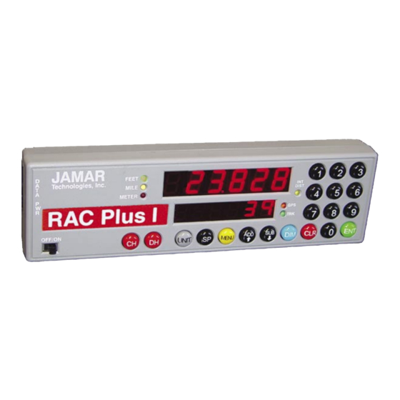
RAC Plus User’s Manual What are the RAC Plus I and Plus II? The JAMAR Technologies Road Analysis Computer (RAC) Models Plus I and Plus II are accurate, easy-to-use distance measuring instruments (DMI) that use state-of-the-art microprocessor technology. The RAC Plus I and... -
Page 7: How Do They Work
Chapter 1 — Introduction How do they work? To use the RAC Plus I or Plus II DMI to accurately measure distance, either a modular distance sensor (MDS) or mechanical transmission sensor is used to send pulses to the DMI. The Quick-Kit, which is a modified version of the MDS, can also be used. -
Page 8: Quick Start Guide
RAC Plus User’s Manual Quick Start Guide The RAC Plus I and II DMIs will allow you to accurately measure distance quickly and easily. However, before you can do this a few basic steps must be taken to ensure that you get the optimum performance from your in- strument. -
Page 9: Installation
Chapter 2 — Installation Chapter 2 Installation... -
Page 10: Before You Begin
RAC Plus User’s Manual Before You Begin Note: The following instructions are for installing a RAC with a Modular Distance Sensor. If you are installing a different type of sensor, refer to the instructions that came with the sensor itself. The JAMAR RAC Plus I and Plus II distance measuring instruments (DMI) are very reliable instruments. -
Page 11: Installing The Modular Distance Sensor
Chapter 2 — Installation Installing the Modular Distance Sensor Most vehicles (1992 and newer) have an electronic speed output rather than a mechanical speedometer cable coming from the transmission. With these vehicles you will need to install either a Modular Distance Sensor (MDS) Vehicle Kit or a Modular Distance Sensor Quick Kit. - Page 12 RAC Plus User’s Manual other wires pass through the firewall. If you cannot locate an existing hole, CAREFULLY drill a small hole large enough for both the VSS cable and the +12Volt/Ground wires. EXTREME CAUTION must be taken to insure you do not drill into anything mounted on the opposite side of the firewall or cut any existing wiring.
- Page 13 Chapter 2 — Installation is switched off with the ignition key. We also recommend the circuit should have as few devices as possible to avoid voltage fluctuations from Turn Signals, Brake Lights, etc. Plug the power cable Fig. 2.4 –Power Plug-in into the hole labeled Power on the MDS, as shown in Figure 2.4.
- Page 14 RAC Plus User’s Manual RAC Connector The number of pulses per mile from a vehicle will vary with the make and model. Your calibration factor should be between .500 and 1.200. If not, adjust the rotary switch then recalibrate to reach a calibration number within this range.
-
Page 15: Installing The Rac Instrument
Installing the RAC Instrument The compact case design of the RAC Plus allows mounting of it in a num- ber of convenient locations. Popular locations include on the front of the dashboard, above or below the dashboard, or on the windshield using the optional windshield mounting bracket. - Page 16 RAC Plus User’s Manual...
-
Page 17: Calibration
Chapter 3 — Calibration Chapter 3 Calibration... -
Page 18: Automatic Calibration Procedure
RAC Plus User’s Manual Automatic Calibration Procedure In order to accurately measure distance, your RAC Plus must know the exact distance that the vehicle will travel based on pulses from the vehicle's speed sensor. The calibration number is the automatic calculation that represents the number of pulses received over a set distance. - Page 19 Chapter 3 — Calibration Step 2 Press the Menu key, the # 1 key and Enter. At this point, the unit of mea- surement will automatically change to feet. You can then select the vehicle number that this calibration will be Fig.
- Page 20 RAC Plus User’s Manual Step 7 Press Enter and the unit of measurement will return to your desired unit of feet, mile or meter. Press Enter again to exit the menu function and return to normal operation. Your calibration number for the vehicle selected is now stored in the RAC's nonvolatile (permanent) memory.
-
Page 21: If Your Rac Fails To Calibrate
Chapter 3 — Calibration If Your RAC Fails to Calibrate If your RAC fails to count during calibration, perform the following op- erational checks: Step 1 Locate the Sensor Test button on the front upper right of the MDS, shown in Figure 3.5. - Page 22 RAC Plus User’s Manual Step 2 The Tap Test will determine if the dis- tance pulses being sent from the MDS are getting to, and being processed by, the RAC. The Tap Test is performed using the rotary switch shown in figure 3.6.
-
Page 23: Manual Calibration Procedure
Manual Calibration Procedure It is very common to share one RAC on a plug-in basis between a number of different vehicles that have been equipped to accept the instrument. Installing additional vehicle kits on other vehicles is an inexpensive and cost effective means to greatly expand your measuring capabilities. - Page 24 RAC Plus User’s Manual Step 3 Press the Enter key and the current cali- bration number for the vehicle selected will be displayed. Press the Clear key (CLR) to clear the current number. Fig. 3.9 Calibration Number Cleared Step 4 Using the numeric keys, key in the de- sired calibration number for the vehicle selected.
-
Page 25: Key Functions & Operating Procedures
Chapter 4 — Key Functions & Operating Procedures Chapter 4 Key Functions & Operating Procedures... -
Page 26: Rac Plus Key Functions
RAC Plus Key Functions Fig. 4.1 — RAC Plus Key Layout Your RAC Plus series DMI has been designed for simple operation, using large individual keys which provide a click and tone feedback. The two 6-digit high-intensity LED display windows (exclusive to the RAC Plus series) allow flexibility in displaying data to you. - Page 27 Chapter 4 — Key Functions & Operating Procedures Display Hold will stop the display from updating while the RAC will continue to accumulate distance internally. When in Display Hold, DH will be displayed in D-2. If speed is also Display being displayed, it will continue as DH does not freeze the Hold speed display.
- Page 28 RAC Plus User’s Manual The Sub key instructs the RAC to count down. When in this mode, the LED indicator for the active unit of measurement will flash to indicate that you are subtracting distance. Should Subtract you count down to zero (0), the RAC will provide a tone and automatically begin counting up.
-
Page 29: Rac Plus Menu Functions
Chapter 4 — Key Functions & Operating Procedures RAC Plus Menu Functions The Menu key of the RAC allows you to select from a variety of functions. After pressing the Menu button, the Add and Sub keys can be used to scroll through the options, which are displayed in D-2. - Page 30 RAC Plus User’s Manual Menu 4 - Clock Set The RAC Plus will compute & display time as either elapsed time from when the instrument was powered up, or real time if the timer has been set. The timer starts automatically at zero when the RAC is powered-up. Time is displayed in D-1 as hh.mm.ss.
- Page 31 Chapter 4 — Key Functions & Operating Procedures Note: To view the Clock/Timer while in the normal measuring mode (not as a Menu function), press the #1 key. D-1 will then display the clock/timer in hh.mm.ss format. Press the #1 key again to toggle back to distance. This function does not interrupt the distance count.
- Page 32 RAC Plus User’s Manual Step 2 Using the numeric keys, enter the interval distance that you want the DPO signal generated, based on your selected unit of measurement (feet, mile, meter). Fig. 4.9 — DPO Distance Entered Step 3 Press the Enter key and you will be prompted to enter how long the DPO signal should last.
- Page 33 Chapter 4 — Key Functions & Operating Procedures To turn off the DPO signal: Step 1 Press the Menu key, the #5 key then Enter. The current DPO interval dis- tance is then displayed in D-1. Fig. 4.13 — Current DPO Distance Step 2 Press the CLR (clear) key and the DPO distance is removed.
- Page 34 RAC Plus User’s Manual Menu 6 - Memory Store Note: This option is only available with the RAC Plus II. It is not available in the RAC Plus I. The RAC Plus II has the unique and exclusive capability to store 3500 events in its internal memory.
- Page 35 Chapter 4 — Key Functions & Operating Procedures Step 4 Once you have selected the identifier you want, press Enter. At this time, if you wish to start at a distance other then zero, you can enter a starting distance using the numeric keys.
- Page 36 RAC Plus User’s Manual Enter. The event code, distance, speed and time (elapsed or real) are stored in memory. There is a short delay (1/2 second) when you press Enter before you can key in another event code. However, the code you entered is written to memory at the instant you press Enter.
- Page 37 Chapter 4 — Key Functions & Operating Procedures Menu 7 - Memory Status Note: This option is only available with the RAC Plus II. It is not available in the RAC Plus I. If you are conducting numerous field surveys before downloading the data to a computer, you may want to check the status of the RAC Plus II's memory from time to time to make sure you have enough memory left for a new survey.
- Page 38 RAC Plus User’s Manual Menu 8 - Memory Erase Note: This option is only available with the RAC Plus II. It is not available in the RAC Plus I. This feature allows you to clear all memory locations that have been stored in the RAC Plus II.
-
Page 39: Rac Plus Additional Features
Chapter 4 — Key Functions & Operating Procedures RAC Plus Additional Features Interval Distance This feature allows you to determine distance between points of interest, such as telephone poles, signs, pavement markings, etc. You can activate Interval Distance at any time as long as you are in the normal measuring mode and not using the menu functions. - Page 40 RAC Plus User’s Manual 4-16...
-
Page 41: Troubleshooting
Chapter 5 — Troubleshooting Chapter 5 Troubleshooting... -
Page 42: Frequently Asked Questions
RAC Plus User’s Manual Frequently Asked Questions Q. My RAC will not count. What’s wrong? A. In most cases, when a RAC Plus won’t count, it is not the unit itself that has the problem. It is usually a problem with the interface sensor or wiring. Check the following: 1. - Page 43 Chapter 5 — Troubleshooting 4. Perform a Tap Test. The Tap Test will determine if the distance pulses being sent from the MDS are getting to, and being processed by, the RAC. The Tap Test is performed using the rotary switch on the MDS.
- Page 44 RAC Plus User’s Manual Q. My RAC will not turn on. What’s wrong? A. There are several possible causes for this. 1. You may have a loose connection. Double check all connections at the MDS and RAC to make sure they are tight and at the correct locations.
-
Page 45: Appendix
Appendix Appendix... -
Page 46: Connection And Output Formats
RAC Plus User’s Manual Connection and Output Formats Power Connector Pin 1 (Yellow) +12 VDC Pin 2 (Green) Sensor Input Pin 3 (Red) Pin 4 (Black) Signal Ground 4 3 2 1 Memory/Serial (RS-232) Output Since the RAC Plus II has internal memory of up to 3500 events, it is not practical to try to view the data on the display on an event by event basis. - Page 47 • Export data in a variety of formats • Allows real-time data collection from the RAC Plus II to your laptop or PDA (custom • Map data Refer to the WinRAC Plus manual for specific information on how to retrieve and process data from the RAC Plus II.
-
Page 48: Specifications
Dimensions: 7.8"W x 2.3"H x 1.2" D Weight: 6.5 oz. Operating Temperature: 0°C to 75°C Warranty: 5-year instrument warranty. Example: JAMAR Technologies RAC Plus I RAC Plus II Specifications (In addition to the above) Memory: Storage up to 3500 Event locations, 0-9999 Event code identifiers, Distance, Time &... -
Page 49: Glossary
Glossary Refer to the page number listed after each entry for more information. Add — black button used to count up or add value to the screen on the RAC. Page 4-3. Dim — blue button on the RAC, it is used to change the brightness of the display. - Page 50 RAC Plus User’s Manual Glossary LED — stands for light emitting diode, the display used with the JAMAR RAC Plus series. Page A-4. Menu — yellow button on the RAC which is used to access many of its operation functions. Page 4-3.
-
Page 51: Vehicle Calibration Record
Vehicle Calibration Record Date: Date: _________________________ _________________________ Veh. No: Veh. No: ______________________ ______________________ Cal. Factor: _________________ Cal. Factor: _________________ Veh. Odometer: Veh. Odometer: _______________ _______________ User Initials: ________________ User Initials: ________________ Date: Date: _________________________ _________________________ Veh. No: Veh. No: ______________________ ______________________ Cal. - Page 52 RAC Plus User’s Manual...
Need help?
Do you have a question about the RAC Plus Series and is the answer not in the manual?
Questions and answers