Table of Contents
Advertisement
Advertisement
Table of Contents

Related Manuals for WABCO OptiTire


Summary of Contents for WABCO OptiTire
- Page 1 OptiTire TIRE PRESSURE MONITORING FOR COMMERCIAL VEHICLES SYSTEM DESCRIPTION...
-
Page 3: Table Of Contents
Basic OptiTire function ........ - Page 4 10.2 Replacement and repair ............63 10.2.1 Replacing an IVTM ECU with an OptiTire ECU ..............63 10.2.2...
-
Page 5: General Information
(French: Accord européen relatif au transport international des marchandises Dangereuses par Route); European agreement concerning the international carriage of dangerous goods by road Controller Area Network; asynchronous serial bus system for networking control units in vehicles ECAS Electronically Controlled Air Suspension Electronic Control Unit Ground; earth TEBS Electronic Braking System for Trailers Vario-Compact-System; compactly structured ABS for trailers Wheel Internal Sensor Wheel Sensor 2; external wheel sensor or module Purpose of this document This document describes the function and installation of the OptiTire tire pressure monitoring system. Copyright and trademark notice The content, particularly technical information, descriptions and figures, corresponds to the state current at the time of printing and is subject to change without notice. This document, including all its parts, in particular texts and figures, is protected by copyright. Use outside the statutory or contractual limits require authorisation by the copyright owner. All rights reserved. Any brand names, even if not indicated as such, are subject to the rules of the trademark and labelling rights. Symbols used in this document Indicates a potentially hazardous situation... - Page 6 – Follow the instructions in this warning note to avoid any material damage. Important information, instructions and/or tips that you must always observe. Reference to information on the internet – Action step Ö Consequence of an action List „ Technical documents – Open the WABCO INFORM online product catalogue: http://inform.wabco-auto.com – Search for documents by entering the document number. The WABCO online product catalogue INFORM provides you with convenient access to the complete technical documentation. All documents are available in PDF format. Please contact your WABCO partner for printed versions. Please note that the publications are not always available in all language versions. DOCUMENT TITLE DOCUMENT NUMBER OptiTire – System Description...
- Page 7 As a leading supplier to the industry, WABCO collaborates with the world’s leading original equipment manufacturers, and has the experience and capacities required to also satisfy the most stringent production standards. The quality of every genuine WABCO part is supported by: Tooling made for serial production „ Regular audits of suppliers „ Exhaustive end-of-line tests „ Quality standards < 50 PPM „ Installing replica parts can cost lives – genuine WABCO parts protect your business. WABCO additional services The package you will get with a genuine WABCO part: 24-month product warranty „ Overnight delivery „ Technical support from WABCO „ Professional training courses from the WABCO Academy „ Access to diagnostics tools and support from the WABCO Service Partner „...
- Page 8 General information Your direct contact to WABCO In addition to our online services, trained members of staff are there to help you at our WABCO Service Partners to directly answer any technical or business- related questions you may have. Contact us if you need assistance: Find the right product „ Diagnosis support „ Training „ System support „ Order management „ You can find your WABCO partner here: http://www.wabco-auto.com/en/how-to-find-us/contact/...
-
Page 9: Safety Information
Safety information Safety information Observe all required provisions and instructions: Read this publication carefully. „ Adhere to all instructions, information and safety information to prevent injury to persons and damage to property. WABCO will only guarantee the safety, reliability and performance of their products and systems if all the information in this publication is adhered to. Always abide by the vehicle manufacturer's specifications and instructions. „ Observe all accident regulations of the respective company as well as „ regional and national regulations. Make provisions for a safe work environment: Only trained and qualified technicians may carry out work on the vehicle. „ Use personal protective equipment if required (safety goggles, respiratory „ protection, ear protectors, etc.). Ensure that the workplace is dry and provided with sufficient lighting. „ Pedal actuations can lead to severe injuries if persons are in the vicinity of „ the vehicle. Make sure that pedals cannot be actuated as follows: – Switch the transmission to "neutral" and actuate the park brake. -
Page 10: Introduction
Introduction Introduction WABCO OptiTire™ is the next generation of tire pressure monitoring for commercial vehicles and replaces the predecessor system IVTM. OptiTire™ was specially developed to reduce the running costs for fleets and increase safety. Reduced downtimes, extended tire life The need to maintain the correct tire pressure seems self-evident, but in reality the tire pressure is checked far too infrequently. Time pressure, inattention and complacency are some of the reasons for this. An official study has found that more than 30% of all truck breakdowns are caused by tire issues. Further studies have shown that even 15% over- or under-inflation can reduce the life of a tire by more than 10%. With under-inflated tires there is an increased risk of sustained overheating. This can cause terminal damage to the casing. WABCO OptiTire helps to maintain the correct tire pressure and to detect slow punctures early. Downtimes Tire damage is the most frequent reason for commercial vehicle vehicles to be out of service. Sonstiges Verbrauchsstoffe Reifen Bremsen 32 % Motor 21 % Elektrik 29 % Cut fuel costs, minimise CO emissions Fuel is the largest variable cost for fleet operators. With diesel prices more... - Page 11 Zu hoher Druck -40% -30% Zu niedriger Druck Zu hoher Druck -50% -40% Abweichung vom empfohlenen Reifendruck [%] -50% Abweichung vom empfohlenen Reifendruck [%] Reduce risk, improve safety Incorrect tire pressure is dangerous and may entail the following risks: a tire failure „ a deterioration in vehicle handling „ extended braking distances „ WABCO’s OptiTire helps maintain tire pressure at the recommended level, preventing tire damage and enhancing fleet safety. OptiTire cannot announce sudden, extreme tire damage caused by external effects.
-
Page 12: System Description
System description System description This chapter describes how the OptiTire system operates. Furthermore, you will also obtain information concerning technical reports for installing and retrofitting. Basic OptiTire function Solo bus LEGEND Sensors: external sensor WM2 (A1) or internal sensor WIS (A2) Electronic Control Unit (ECU) Display Measurement The tire pressure is measured by sensors. The measured values are repeatedly transmitted to the electronic control unit by radio signal. The actual tire pressure of each wheel is transmitted to a central ECU. The signals of all wheels are evaluated there and the information is conveyed to a display in the driver's cab. Evaluating In the ECU, the measured values are compared to one another and to standard values stored as a parameter set in the ECU. A single OptiTire ECU can monitor up to 20 wheels + 2 spare wheels. Dual tires are sensed separately. A warning is signalled in the event of a critical deviation. -
Page 13: Configuration For Bus And Towing Vehicle
Configuration for bus and towing vehicle Selection of OptiTire components depends on vehicle type, type and number of wheels and type of systems connected to OptiTire but not on the vehicle system voltage. Trucks, buses or articulated buses are equipped with the ECU (WABCO part number: 446 220 100 0). Display In the case of original equipment, the tire pressures are retrieved by a central on-board computer via CAN and displayed on an integrated display in the dashboard. If retrofitted, the WABCO display (WABCO part number: 446 221 000 0) is used for retrieving the tire pressures. Sensors Select sensors and counterweights according to their axle configuration. The table contains components for three vehicle type as examples. Further information in the chapter "Components",see chapter 5 "Components", page WABCO Bridge configurator WABCO offers an online configurator "WABCO Bridge" for the configuration of OptiTire for different vehicles (towing vehicle, bus, semitrailer). – Open the myWABCO website: http://am.wabco-auto.com/welcome/ Help on logging in can be obtained by pressing the Step-by-step instructions button. After the successful registration you can use the online configurator WABCO Bridge via myWABCO to carry out your own configuration of the OptiTire system. Please contact your WABCO partner if you have any questions. - Page 14 System description Example: Parts list for bus / towing vehicle (with external sensors WM2) WABCO PART ARTICULATED NUMBER COMPONENT COMMENT BUS 6X2 446 220 100 0 Communication with trailer ECU / warning lamps 446 220 000 4 Mount Support for mounting the ECU 446 221 000 0 Display Display of warning messages and...
-
Page 15: Configuration For Trailers
System description Configuration for trailers Transmission types To display the OptiTire data of the trailer in the driver’s cabin, both the trailer and towing vehicle must be equipped with OptiTire in combination with the external sensor WM2 if communication is implemented via radio link. Alternatively, the trailer data can be displayed in the towing vehicle if it is equipped with an integrated display. When the trailer is also equipped with WABCO Trailer EBS, the data can transferred to the towing vehicle’s central computer via CAN. The following illustrations compare both transmission types, wireless connection and CAN bus, with each other. Data transmission via a CAN bus Data transmission via radio link The data can only be transmitted via a radio link if both the towing vehicle and the trailer are equipped with external sensors. LEGEND Display Sensors Wireless connection Trailer ECU Integrated display Central computer TEBS modulator In combination with external sensor in towing vehicle and trailer... - Page 16 System description Stand-alone trailer towing operation If the trailer should be independently equipped with OptiTire , the pressure release can be carried out via telemetry or the vehicles own display. When using the OptiTire display, it requires a special box for splash protection or another protected installation position. The WABCO SmartBoard can be installed as an alternative. The driver cannot receive fault messages without OptiTire support while the towing vehicle is in motion. You will find further information in the TEBS E system descriptionsee section "Technical documents" on page 6. OptiTire with several trailers Equipment of tractor/trailer combinations with more than one trailer is possible. Tractor/trailer combinations with two trailers can still be made with wireless connections; road trains need CAN bus connection with special ECUs. Please contact your WABCO partner for more information. OptiTire with TEBS D or TEBS E The installation in a vehicle with TEBS D or TEBS E is simple because in this case only pre-assembled cables need to plugged in. Other systems would require open wiring that needs to be enclosed by protective housing. You will find further information in the TEBS E system descriptionsee section "Technical documents" on page 6.
- Page 17 Circuit diagram 841 801 943 0 "Trailer ABS VCS" Cable position 8 (WABCO part number: 449 314 XXX 0) is opened and connected to cable position 3 (WABCO part number: 449 674 273 0) and a line to the stop light. Note: If the OptiTire system is installed instead of the IVTM system, additionally use the adapter cable with the WABCO part number: 894 600 001 2. Circuit diagram 841 801 941 0 "Trailer EBS without CAN connection"...
- Page 18 480 102 014 0) 2 Cable family (WABCO part number: 449 377 XXX 0) 3 SmartBoard (WABCO part number: 446 192 110 0) 4 OptiTire -ECU 5 Distributor housing Note: If the OptiTire system is installed instead of the IVTM system, additionally use the adapter cable with the WABCO part number: 894 600 001 2. Circuit diagram 841 802 066 0 "Trailer EBS E" The circuit diagram shows different connection options with Trailer EBS E.
-
Page 19: Optitire Tm In Trailer Operation
System description 4.3.1 OptiTire in trailer operation Operating mode The OptiTire system in the trailer operates self-sufficiently if supplied with power. Tire pressures can be displayed with the SmartBoard. In addition, the tire pressure information is transmitted to the towing vehicle via the ISO 7638 CAN connection. Not all towing vehicles display the tire pressures transmitted via CAN in the dashboard. Please contact the manufacturer of the towing vehicle if you have any questions on this subject. Alternatively the trailer’s tire pressures can be transmitted to the OptiTire the towing vehicle by means of a radio. This wireless transmission can only occur if the external sensors are configured on both vehicles. Apart from the display of trailer tire data in the towing vehicle, this data can also be transmitted directly to the haulage company by means of telematics. The combination of OptiTire with TX-TRAILERGUARD is of particular interest if the trailer is transported by subcontractors or rented to third parties. Automatic trailer recognition The towing vehicle ECU automatically detects the combination with a trailer ECU: The stop light is enabled on towing vehicle and trailer when hitting the brake. The trailer ECU radios a signal with this voltage pulse that is expected by the towing vehicle's ECU that instant. The towing vehicle thus clearly detects that the trailer belongs to the tractor/trailer combination and subsequently transmits trailer ECU messages to the display. As trailers are usually not permanently powered, it is possible that due to the frequency of sensor transmission the tire pressure data for all the wheels of the trailer is not available in the display for up to 21 minutes after starting the drive –... -
Page 20: Expert's Report / Certificates
System description Expert’s report / certificates Expert’s reports / Certificates for mounting and additional mounting of OptiTire are available, which significantly facilitate approval of vehicle registration papers. Customers must also include the relevant details in the operating instructions. – Open the WABCO INFORM online product catalogue: http://inform.wabco-auto.com – Search for the desired expert’s report / certificate by entering the index word "OptiTire". 4.4.1 ATEX As the WM2 has its own battery and is attached to the outside of the wheel, it falls under the ATEX directive to be used as explosion-proof equipment for potentially explosive gas atmospheres up to zone 1. It fulfils the relevant requirements. Expert’s report / certificate WM2: Associated EU type test certificate „ TÜV 04 ATEX 2418 X Application area ADR (G: potentially explosive gas „ atmospheres): II 2G Ex ib IIC T4 The device is rated as being a small piece of electrical equipment, and therefore the marking does not contain the complete information in accordance with directives or standards. The manufacturer of the sensor is WABCO GmbH, Am Lindener Hafen 21, 30453 Hanover. -
Page 21: Optitire Rf Declaration Of Conformity
System description 4.4.3 OptiTire RF declaration of conformity "This device complies with Part 15 of the FCC Rules. Operation is subject to the following two conditions: (1) this device may not cause harmful interference, and (2) this device must accept any interference received, including interference that may cause undesired operation" "This device complies with Industry Canada’s licence-exempt RSSs. Operation is subject to the following two conditions: (1) This device may not cause interference; and (2) This device must accept any interference, including interference that may cause undesired operation of the device." „Le présent appareil est conforme aux CNR d’Industrie Canada applicables aux appareils radio exempts de licence. L’exploitation est autorisée aux deux conditions suivantes: 1) l’appareil ne doit pas produire de brouillage; 2) l’utilisateur de l’appareil doit accepter tout brouillage radioélectrique subi, même si le brouillage est susceptible d’en compromettre le fonctionnement." CAUTION TO USERS: "Changes or modifications not expressly approved by the party responsible for compliance could void the user’s authority to operate the equipment."... -
Page 22: Components
Components Components This component description details the properties of basic components. Outline drawings – Open the WABCO INFORM online product catalogue: http://inform.wabco-auto.com – Search for the desired outline drawing by entering the product number of the component. OptiTire can be interrupted in its function if other devices or systems in the vicinity are also transmitting in the area of 433 MHz. These can be radio sets, radio remote controls (e.g. for door actuation, cranes, forklift), insufficiently shielded electrical drives with high power or other radio transmitters. When the OptiTire system is removed from the area of interference, the function is guaranteed again. Sensors General information and technical data SENSORS (APPLIES TO INTERNAL AND EXTERNAL SENSOR) Material Plastic (moulded and self-contained) Pressure sensor „ Integrated components Circuit for evaluation „... -
Page 23: The External Sensor (Wm2)
Risk due to incorrect handling CAUTION Any changes or manipulation to the sensor of any type, especially attempts made to change the battery will destroy the device and may lead to injuries. – Do not unscrew or remove the sensor from the bracket. Information and technical data THE EXTERNAL SENSOR (WM2) Variants of "External sensors"see page 24. WABCO part numbers Depending on rim crank, use of the normal external sensor or the so-called L-shape or T-shape version is recommended Pressure range 2 to 14 bar correspond to the nominal values of pressures from 3 to 10 bar Temperature range -40°C to +90°C, 24h up to 120°C Depends on the part number and availability of an acceleration sensor „... - Page 24 Components Function The external sensor, which is fastened to the existing wheel bolts, enables a wheel change without the need to reconfigure the system. The external sensor is also predestined for retrofitting due to the way it is installed. Please note that special external sensor and PA tube variants must be used for different rims and installation locations. With twin wheels and Super Single rims, problems may occur with the radio transmission due to the immersion depth. To ensure a good quality of reception, T-shaped external sensors should be used (WABCO part numbers: 960 731 031 0 or 960 731 041 0). "External sensors WM2" variants The various types of external sensors are illustrated in the table: HOLE, WABCO PART WHEEL APPLICATION NUMBER BOLT BOLT HOLE Ø ANGLE FIGURE Trailer: Independent wheel 960 731 011 0 26 mm 335 mm 0° (no Super-Single) Trailer: Independent wheel (no Super-Single), 20° 960 731 013 0...
- Page 25 Components HOLE, WABCO PART WHEEL APPLICATION NUMBER BOLT BOLT HOLE Ø ANGLE FIGURE Twin tires, Super-Single 960 731 041 0 32 mm 335 mm 70° Towing vehicle: Front axle, 960 731 051 0 26 mm 335 mm 60° load axle Towing vehicle: Front axle, 960 731 053 0 32 mm 335 mm 0° load axle Towing vehicle: Front axle,...
- Page 26 Components HOLE, WABCO PART WHEEL APPLICATION NUMBER BOLT BOLT HOLE Ø ANGLE FIGURE Towing vehicle: Front axle, 960 731 075 0 26 mm 285.75 mm 33° load axle Twin tires, Super-Single 960 731 081 0 26 mm 225 mm 70° 960 905 822 4 26 mm Counterweight for L-shape 335 mm 0° sensor 960 905 823 4...
- Page 27 Components Connecting tube The external sensors must be permanently connected to the tires for sensing tire pressures. Use WABCO pre-assembled PA tubes for this purpose. The connection does not have to be disconnected for inflating the tires as valves for inflating the tire are located on the external sensors. Depending on wear situation, a replacement of the PA tube is recommended after 1,000,000 km. Various types of PA tubes are illustrated in the chart: "PA tube" variants WABCO PART NUMBER FIGURE ORDER NUMBER FIGURE 960 731 800 0 960 731 810 0 960 731 801 0 960 731 816 0 960 731 802 0...
-
Page 28: The Internal Sensor (Wis)
– Run a system test when you have replaced the external sensors with internal sensors. – Install the ECU receiver in a more suitable place if the functionality is impaired. Information and technical data THE INTERNAL SENSOR (WIS) WABCO part numbers 960 732 000 0 Pressure range 0 to 13 bar correspond to the nominal values of pressures from 3 to 10 bar... - Page 29 Components Valve sets The following valve sets (consisting of valve, nut and locking screw) are available: APPLICATION WABCO PART NUMBER SURFACE OUTER CONTOUR Standard steel rims 17 to 22.5" 960 732 100 0 Brass ETRTO V0.07.3 Standard steel rims 17 to 22.5", tighter 960 732 101 0 Nickel ETRTO V3.22.1 rim crank Standard steel rims 17 to 22.5", 960 732 102 0 Nickel ETRTO V3.22.1 additional 5° inclined section "Rim" overview Valve sets are available for the following rims. This overview is for example only.
- Page 30 Components RIM SIZE MATERIAL SUPPLIER RIM NO. VALVE SET 960 732 100 0 / 22.50 x 11.75 Steel Kronprinz 15083 960 732 101 0 960 732 100 0 / 22.50 x 11.75 Steel Kronprinz 15095 960 732 101 0 22.50 x 09.00 Steel Kronprinz 852XA...
-
Page 31: Ecu - The Electronic Control Unit
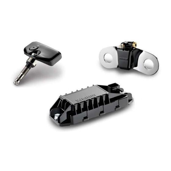
Purpose and function The ECU receives the sensor signals and immediately recognises all changes from programmed nominal tire pressure values by combined comparison with threshold pressure values and pressure changes. Incorrect values of tire pressures are already displayed before departure (if ECU is permanently powered). Faults occurring during operation are stored in the electronic unit for diagnostic purposes. The ECU is mounted to chassis in central part of vehicle, so that perfect radio contact with all sensors and between trailer ECU and towing vehicle ECU is ensured. You should use special brackets for good radio contact. Fixing bracket (WABCO part number: 446 220 000 4) Radio contact is provided by antenna integrated in the ECU housing that guarantees interference-free pressure signal reception from all sensors. Information and technical data ECU – THE ELECTRONIC CONTROL UNIT 446 220 100 0: Towing vehicle and bus „ 446 220 110 0: Trailer and trailer train (can be cascaded up to 5 times with „ 22 sensors respectively, must be parametrized by diagnosis) WABCO part numbers ECUs essentially differ by radio communication signal structure and CAN bus (ID) connection. External distinguishing mark by type label only. -
Page 32: Wabco Display
Components WABCO display Purpose and function The display is used for indication and retrieval of all pressure and leakage information for the and checking all necessary information on the OptiTire system. It operates in combination with the OptiTire ECU (WABCO part number: 446 220 100 0). It is connected to ECU via CAN bus. All tire pressures can be queried by pressing a buttonsee chapter "9.3 Checking pressure values" on page 57. Manual checks of the tire pressure are superfluous. Faulty tire pressures should be corrected directly at the tire valve. Since warnings are also signalised acoustically, the display does not need to be installed within driver's direct field of vision. Optical warnings are indicated by integrated lights: red (stop immediately) „ yellow (drive slowly) „ Information and technical data WABCO DISPLAY 446 221 000 0 (standard version) WABCO part numbers 446 221 100 0 (special variant for straddle carrier) Supply voltage 12 or 24 volts Display... -
Page 33: Connecting Cables
Components Connecting cables For towing vehicle / bus OptiTire is connected to the vehicle wiring in two sections: The first section comprises the connection of the ECU to the distribution „ element in the vicinity of the driver's workplace. This section is splash-proof allowing external installation on vehicle. The OptiTire cables are connected via the adapter cable (WABCO part number: 894 600 001 2). The second section is a cable set designed exclusively for the interior. „ Here there is a split connection from the connection of the first cable to the WABCO display, to the diagnostic port, and a connection to the vehicle wiring terminals using free cable ends. Basic wiring principle for towing vehicle / bus is displayed in the following illustration: Wiring of towing vehicle LEGEND Display Diagnosis Vehicle electrical system ECU (via adapter cable with WABCO part number: 894 600 001 2) External Internal... - Page 34 +24 V or 12 V Ignition yellow & grey grey Stop light / warning yellow lamp 2 Warning lamp 1 green Connection to +12 V/24 V and ignition must be fused with 5 ampere fuses. Since OptiTire has a low current consumption an existing fused circuit can normally be integrated as well. Cable set "Towing vehicle 7-pin" 894 607 390 0 The 7-pin wiring is provided in accordance with the cable set (WABCO part number: 894 607 390 0) see figure "Towing vehicle wiring". Pin assignment on the connecting plugs corresponds to the 5-pin variant. In addition, either a connection to the stop light (for synchronising with the trailer ECU) or connection of one or two warning lamps is possible. Cable set "Towing vehicle 5-pin" 894 607 295 0 A simpler wiring (WABCO part number: 894 607 295 0) is provided as a 5-pin variant for retrofitting in buses.
- Page 35 Components Trailer wiring LEGEND ECU (via adapter cable with WABCO part number: 894 600 001 2) Brown: Ground Red: +12 V/24 V White: Stop light Diagnosis...
-
Page 36: Installation
Installation Installation In this chapter you will learn how the OptiTire is installed your vehicle. Observe all safety instructions when carrying out assembly work on the vehicle. WABCO Bridge configurator – Open the myWABCO website: http://am.wabco-auto.com/welcome/ Help on logging in can be obtained by pressing the Step-by-step instructions button. After the successful registration you can use the online configurator WABCO Bridge via myWABCO to carry out your own configuration of the OptiTire system. Please contact your WABCO partner if you have any questions. Safety information – Observe the occupational health and safety regulations of the respective country, the workshop as well as the vehicle manufacturer's instructions. Risk of accident due to loose wheel nuts Loose wheel nuts may lead to accidents when driving on roads. – Wheel nuts must be tightened with torque specified by vehicle manufacturer. – Check the tightness of the wheel nuts after 500 km. Risk of accident due to unsecured vehicle Vehicles not secured may roll away during the assembly. This might lead to... -
Page 37: Assembly Of The External Sensors Wm2
Installation Assembly of the external sensors WM2 The vehicle does not need to be jacked up when only four wheel nuts are removed. Preparing assembly – Please read the chapterssee chapter "5.1.1 The external sensor (WM2)" on page 23 andsee chapter 4.5 "Connecting tubes", page 24. – If necessary, also remove the rim protecting ring. Assembly of the external sensor – Loosen and remove two wheel nuts positioned next to each other near to the valve. – Check if the position of the external sensor is suitable for connecting to the PA tube and the valve. The PA tube should be able to be guided to the tire valve without stretching, upsetting deformation or twisting. – Position the external sensor on the wheel bolts. – Screw the wheel nuts back on. – Remove the white protective cap from the pressure connection. Assembly of the counterweight – Loosen the wheel nuts that are exactly opposite of the external sensor (trailer). If the counterweight has 3 holes, loosen another nut clockwise to the left (front axle, load axlesee section "Counterweight" on page 26). - Page 38 – Avoid excess lengths to prevent undesired vibrations. – Avoid moisture in the PA tube or at the pressure port of the external sensor. – Hold the PA tube with the connection to the tire valve. – Hold the other end of the PA tube to the external sensor. – Mark the position on the tube where the PA tube sits flush with the edge of the external sensor (e.g. using adhesive tape). – Cut the PA tube (WABCO part number: 960 731 800 0 bis 960 731 802 0) to the required length if necessary. Also consider that the PA tube disappears to 20 mm in the connection. For this purpose, the PA tube should be cut 20 mm behind the marking. Use a suitable right-angled cutting tool, such as those that are also used for shortening plastic brake lines. Tube cutting tool for Tube cutting tool for ø...
- Page 39 Installation – Check that the connection is tight using a leakage indicating spray. Getting external sensor ready for operation – Tighten the wheel nuts crosswise again according to the vehicle manufacturer’s specifications. – Re-tighten the rim protective ring if necessary. Correct assignment of external sensor ID vs. connected wheel is essential for later commissioning. – Note position of installed external sensors on a sheet of paper. – Affix stickers with external sensor ID next to the respective wheel module. – Adjust tires to correct operating pressure according to the vehicle manufacturer's instructions. – Note pertinent nominal pressure values per axle for later nominal pressure parametrization through diagnostic. Avoid standing water or moisture in the filling tool or in the tire inflating device. – Check wheel nuts for tightness after 500 km. Risk of accidents due to loosening the fastening WARNING screws of the external sensor The safe fixing of the wheel module is only possible when the external sensor housing has a tight fit to the bracket.
-
Page 40: Assembly Of The Internal Sensor
Installation Valve extension Do not use plastic valve extensions. These will not remain tight under permanently existing pressure. Twin wheels (outer wheel) Twin wheels (inner wheel) Assembly of the internal sensor Safety information – Always observe the applicable hazard warnings and correct procedures on the assembly machine. This information has priority over these instructions. – Replace the internal sensor if the pressure opening is blocked with foreign bodies. – Make sure that the screw can retain the internal sensor permanently with 4 Nm. – In the case of screws with locking varnish, always use new screws with every assembly. – Never re-tighten self-locking screws and union nuts. – Use self-locking fastening screws only once. – Use the valve that matches the rim. Select the correct valve using an assignment tablesee chapter "5.1.2 The internal sensor (WIS)" on page – Do not apply compressed air, assembly paste, detergents or other cleaners to the internal sensor. - Page 41 Installation Preparing assembly – Read the following chaptersee chapter "5.1.2 The internal sensor (WIS)" on page 28. – Jack up the vehicle at the corresponding wheel positions. – Remove the wheel. – Use a suitable assembly device to remove the tire. It is sufficient to pull the tire over the rime on one side; fee access to the drop-centre and valve is all that is required. – Remove the original tire inflation valve. Assembly of the internal sensor – Fit the suitable tire inflation valve (figure 1). Observe the tightening torque specified for the rim and correct alignment of the valve. Figure 1 – After the valve is fitted, the internal sensor is placed on the valve head on the rim’s inside (figure 2) and fastened with the screw (figure 3). The following must be observed during this procedure: The internal sensor must be aligned parallel to the rim (figures 4 & 5). „ The sensor must make contact over the entire contact area of the valve; „ in addition it must be supported at two other points on the rim (3-point assembly) (figures 6 & 7). The tightening torque is 4 ±0,5 Nm (figures 8 & 9). Always use a torque „ wrench for the exact torque! Figure 2 Figure 3...
- Page 42 Installation Figure 4 Figure 5 Figure 6 Figure 7 In the case of steel rims the internal In the case of aluminium rims sensor sits flat on the rim. only the rear section of the wheel electronics sits on the rim. Figure 8 Figure 9 Correct fit of the internal sensor Incorrect fit of the internal sensor...
- Page 43 Installation Assembly of the tire – Fit the wheel onto the assembly machine that the assembly head is on the opposite side of the valve, i.e. offset by 180° (figure 10). Figure 10 CAUTION Damage to the internal sensor The internal sensor can be damaged by the penetration of fluids. – Make sure that the internal sensor does not come into contact with fluids (e.g. assembly fluid). – Apply assembly fluid to the tire bead and rim flange. – Now push the bead to be fitted onto the rim over the rim flange. During assembly the tire bead must not be pressed against the wheel electronics. Otherwise there is a risk of the internal sensor coming off at the fastening point. – Then pull the second tire bead onto the rim. During this procedure the bead must never be pressed onto the internal sensor or pulled over it. During assembly the assembly head must have a minimum distance of 20 cm to the internal sensor (figure 11). The remaining part of the bead can be pressed over the rim flange in the normal way (figure 12).
-
Page 44: Mounting The Ecu In Bus / Towing Vehicle
Installation Figure 11 Figure 12 – The remove the complete wheel from the assembly machine and inflate it as usual. If a filling bell is used, the tire must not exert any pressure on the internal sensor housing or get stuck on the housing. Assembly of the wheel – Fit the complete wheel to the vehicle. When doing this, apply the tightening torques specified by the vehicle manufacturer. Mounting the ECU in bus / towing vehicle ECU position on vehicle Towing vehicle The ECU connector must point to side (to the right or left) but not up or down. – Choose the fitting position in accordance with the figure "Assembly on the longitudinal beam". – If the vehicle is equipped with a low lying coupling for central axle trailer, install the ECU on the right side of the vehicle, so that the wireless connection to the trailer is not shielded of by the coupling. - Page 45 Installation Assembly on the longitudinal beam – Use threaded rods for hanging assembly at the roof frame in the cabin. – For solo bus: Position the ECU at the centre of the vehicle. – For articulated bus: Position the ECU in front of the articulation in driving direction. Further possible installation positions are: in the roof cove opposite the entrances (if the cover is made of plastic) „ in the roof lining „ with articulated buses, in the rear area of the front section (in the geometric „ centre of all axles) with coaches, also on the luggage compartment (if the luggage compartment „ components are at least in part of wood or plastic) Mounting the ECU – Read the chaptersee chapter 5.2 "ECU – The electronic control unit", page – Mount ECU so that the distance to the sensors is as equal as can be. Select distance to truck driver's cab such that length of ECU cable (8 m) is sufficient to reach driver's cab. In the towing vehicle there is an ideal installation position between the front and rear axles underneath the frame. Maintaining good radio contact the ECU should not be shielded off by metal walls in its direct vicinity, e.g. by a U-section.
-
Page 46: Wiring In Towing Vehicle/Bus
Wiring in towing vehicle/bus Proceed as follows to install the wires of the OptiTire system into the bus or the towing vehicle: – Read the following chaptersee chapter 5.4 "Connecting cables", page – Select the suitable circuit diagramsee chapter 4.2 "Configuration for bus and towing vehicle", page 13. – Attach display to support supplied at a suitable attachment location. The display must not necessarily be located inside driver's direct field of vision. – Fit the diagnostic socket to a suitable attachment location and label it with "Diagnostic OptiTire ". Locations where diagnostic ports are already located would be specially suitable as the attachment location. – Install cables according to the wiring diagram using cable ties in parallel with already existing wiring harnesses. – Form large loops from ample lengths. – Turn off the ignition. – I n the fuse box, search for appropriate fused circuits or connect 5 A "flying" fuses to terminal 15 (ignition) and 30 (U Batt). – Label the flying fuses with "OptiTire ". – Connect the cable set with the fuses. – Connect the ground line to the ground contact. – Connect display and ECU. -
Page 47: Mounting The Ecu In The Trailer
Installation Mounting the ECU in the trailer – Read the following chaptersee chapter 5.2 "ECU – The electronic control unit", page 31. – Determine the best possible installation position, depending on the type of the trailer: Drawbar trailer: „ Install the ECU between the first axle and the middle of the trailer. Semitrailer: „ Mount the ECU at the cross member in the front area, so that this is pointing to the towing vehicle. Central axle trailer: „ Install the ECU in front of the first axle on the right-hand side of the vehicle. For the towing vehicle use the bracket (WABCO part number: 446 220 000 4). Screw on bracket to vehicle. Welding could impede frame stability. – Attach the ECU below on the frame. ECU longitudinal axis must be in parallel with the vehicle axis. Maintaining good radio contact the ECU must not be shielded off by metal walls in its direct vicinity. Semitrailer: Assembly at cross member – Tighten ECU to bracket using torque of 15 ±1.5 Nm. -
Page 48: Wiring In Trailer
Installation Wiring in trailer Proceed as follows to install the wires of the OptiTire into the trailer: – Read the following chaptersee chapter 5.4 "Connecting cables", page – Select the suitable circuit diagramsee chapter 4.3 "Configuration for trailers", page 15. – Fit the diagnostic socket to a suitable attachment location and label it with "Diagnostic OptiTire ". Locations where diagnostic ports are already located would be specially suitable as the attachment location. – De-energize the trailer. Consider any risks of short circuits through batteries inside the vehicle. – Install cables according to the wiring diagram using cable ties in parallel with already existing wiring harnesses. Form large loops from ample lengths. – Connect the OptiTire cabling to the existing cabling. – Connect the ECU. -
Page 49: Requirements For The Start-Up
Requirements for the start-up Requirements for the start-up Training Entering a PIN is required for the parameter settings. Having participated in a course of E-Learning, you can request a PIN for the Diagnostic Software from us. You can then use this personal identification number to enable enhanced functions in the software that allow you to modify the settings in electronic control units. WABCO Academy – Registration for a training course / eLearning – Open the myWABCO website: http://am.wabco-auto.com/welcome/ Help on logging in can be obtained by pressing the Step-by-step instructions button. Once you have successfully registered and logged in you can book training courses and work through E-Learnings via myWABCO. Please contact your WABCO partner if you have any questions. Diagnostic Software With the Diagnostic Software you have the following options: Retrieving the diagnostic memory data „ Retrieving current measured values „ Parameter setting „... -
Page 50: Diagnostic Hardware
TEBS since 2004 VCS II CAN diagnostic cable External diagnostic socket with Diagnostic Interface yellow cap (DI-2) with USB port (for 446 300 348 0 connection to a PC) 449 611 XXX 0 446 301 030 0 TEBS E Premium Installing the Diagnostic Software Proceed as follows to put the OptiTire into operation with the Diagnostic Software: – Make sure that the OptiTire system is installed according to the instructions (see chapter "6 Installation" on page 36). – Connect the computer to the vehicle using the diagnostic cable and Diagnostic Interface. -
Page 51: Start-Up
Start-up Start-up Starting the Diagnostic Software – Start the Diagnostic Software. – Switch on ignition. Ensure power supply of trailer if necessary. – Chose whether a guided selection should take place or the Diagnostic Software should automatically search for connected ECUs. Parameter setting 8.2.1 Reading in a parameter set – This button can be used to read in a parameter set directly. 8.2.2 Selection/entry of parameter data – Click the accompanying button if your wish to enter the parameters yourself. Ö The Parameters window is opened. – Select whether the Module reception should be displayed or an Assignment test should be carried out. "Vehicle configuration" tab – Enter the respective vehicle type and vehicle data. –... -
Page 52: Stimulating The Sensors
Start-up The modules can be assigned by means of a free or sequential assignment. For this purpose a diagnostic message is stimulated for the selected sensors and the corresponding ID is inserted automatically at the selected position: – Under Module assignment, click the Execute button. – Select Sequential (complete installation of a vehicle) or Free module selection (replacement of a wheel or sensor). 8.2.3 Stimulating the sensors Stimulating the external sensors – From the READ OUT SENSOR menu on the WABCO OptiTire handheld tool (WABCO part number: 300 200 001 0), select an external sensor (WM 2.2 TRIG or WM 2.4 TRIG). – Hold the WABCO OptiTire handheld tool near the external sensor. The adjacent wheel may interfere with the radio signal, in which case the respective wheel must be turned. Alternative – For this purpose, touch the housing of each wheel module below the sticker "OptiTire " for 5 seconds using a magnet (2 kg retention force) or using a bar magnet parallel to the OptiTire logo. External sensor with solenoid for simulating the external sensors Stimulating the internal sensors –... -
Page 53: Country-Specific Adjustments
Start-up "Warning lamp configuration" tab – Configure possible warning lamps. For a towing vehicle ECU, only one external warning lamp can be configured. For a trailer ECU, two external warning lamp can currently be configured. 8.2.4 Country-specific adjustments – In the Diagnostic Software, carry out country-specific adjustments, e.g. indication of bar or PSI, use of USA radio protocol (FCC), resolution of the tire message. 8.2.5 Expert parameters As the last parameter setting define the parameters in the Expert parameters window. Expert parameters are available for special applications: – In the Parameter under the module configuration tab activate the Display expert parameters function for this purpose. Ö The Expert parameters window appears. You have the following options: Temperature warning: „ If internal sensors are used, a warning message can be given out when the defined temperature value is exceeded. 100 °C is defined as default here (maximum value: 120 °C). Tire status messages: „... -
Page 54: Finalising Start-Up
Reset and leakage parameter: „ If activated, another page displays the parameters for resetting the leakage algorithm are displayed. DM1 message: „ These parameters define the conditions for sending DM1 messages and whether they should be empty (no event present) or filled (event present) in a fault-free state. Finalising start-up – Delete content of diagnostic memory (start window: Messages - Diagnostic memory). – Check if data has been received from all sensors (start window: Measured values => Module reception). – Print out the start-up log by clicking the accompanying button (Start-up window). – Print the vehicle label onto self-adhesive aluminium foil (WABCO part number: 899 200 922 4) (Start-up window). – Attach the vehicle label to the vehicle where it is protected and legible. – Exit the start-up procedure in the diagnostic software. – Check operation on display and data exchange with towing vehicle respectively. -
Page 55: Operation
Operation Operation In this chapter, the handling of the OptiTire system is described by means of the WABCO display. Additionally installed warning lamps indicate the same warning as the display if parameterised accordingly. Please refer to manufacturer's operating instructions when operating by means of an integrated display. Warning signals The colour of the signal lamp and the type of audio signal indicate the severity of the fault: Red warning lamp / STOP symbol on the WABCO Display and acoustic „ warnings at one minute intervals: Critical fault: The vehicle must be stopped immediately (potential risk to persons and vehicle). Yellow warning lamp / turtle symbol on the WABCO Display and acoustic „ warnings at ten minute intervals: Minor fault: The vehicle speed should be reduced and the tire pressure corrected at the next opportunity. The faults identified by OptiTire are stored in the ECU for diagnostic purposes. Switch on of ignition After the ignition is switched on, the OptiTire system runs a self-test to check that all the internal functions are functioning correctly. All symbols are displayed for one second, all pilot lights and audio signals are enabled. This procedure is repeated twice. Initialisation... - Page 56 Operation After initialisation, if tire pressures are within specified values, the following picture will show for a few seconds: System check The display will change to normal mode if all pressures are correct. Normal mode...
-
Page 57: Checking Pressure Values
Operation Checking pressure values Proceed as follows to display the pressure values of the individual tires: – Press the button with the tire symbol. The axle of which the pressures are displayed, is marked on the display. Left pressure value on the display corresponds to left tire in driving direction. Right pressure value on the display corresponds to left tire in driving direction. Checking pressure values – Repeatedly push button with the tire symbol to display pressure values of further axles. Axles with twin tires have their wheels represented outside and inside one after the other. – Repeatedly push button with the tire symbol to display the axles of the towing vehicle as well as the axles of the towing vehicle. The display will switch back to normal mode if no button has been pushed for a period of 20 seconds. -
Page 58: Display Of Faults
Operation Display of faults When OptiTire detects a fault, an amber or red warning lamp illuminates. Proceed as follows to display the type of fault on the vehicle: – Push button with the question mark after the yellow or red warning lamp lights up. The pressure value of the affected wheel will be indicated and the position on the vehicle is indicated by a flashing wheel icon. If no fault is found, the system does not react when the button with the question mark is pressed. Display of faults If the system warns about several tires the tire with the most serious fault is indicated first. Repeated pressing of the button with the question mark displays further faults. Creeping pressure loss... -
Page 59: Adjusting Tire Pressures
Operation Overview of fault types FAULT DISPLAY ACTION – Stop the vehicle immediately. Extremely low – Look for the cause of the reduced pressure pressure. – If necessary, also change the tire. – Reduce your driving speed. Low pressure – Adjust tire pressure at the next opportunity. – Reduce your driving speed. – Stop the vehicle at the next opportunity. Creeping pressure loss – Look for the cause of the pressure loss. – If necessary, also change the tire. – Reduce your speed for preventing the tire from bursting. – Stop the vehicle at the next opportunity. High pressure – Search for the cause of excess pressure (e.g. defective, overheated brake). -
Page 60: Display Of System Errors
Operation Display of system errors If "IVTM" is represented crossed out then there are one or more system faults. System should be checked in the workshop. No reception Marked wheel has not transmitted pressure value for over one hour. OptiTire has stopped sending warning messages for this wheel, driver needs to check tire pressure on the wheel manually. No reception Repair note With an older system, the sensor battery may be exhausted: – Renew the sensor. – Start operating the new sensor using diagnostic software by setting a new ID in the parameters. If it is a newer system, the radio connection between the sensor and the ECU may be disturbed: – Remove any possible dirt. – Define the installation position of the ECU via diagnosis (position of best reception from all sensors). - Page 61 Operation System failure A system failure has occurred if display shows crossed-out "IVTM". OptiTire does not signal warning messages for any wheel. The driver must check the tire pressures manually on the wheel. System error Repair note – Check the supply voltage of the ground line. – Check the cable connections. – Carry out a system diagnosis. Battery warning If the wheel sensor battery’s end of life has been reached after around 9 years, a battery warning is set around half a year beforehand. This is indicated in the display by a flashing sensor and a corresponding battery symbol. No warning lamp is indicated.
-
Page 62: Display Via Smartboard
Operation Display via SmartBoard WABCO SmartBoard 446 192 110 0 (with integrated battery) WABCO part numbers 446 192 111 0 (for hazardous goods vehicles) The SmartBoard is a display and operating console that can be used to display the following information relating to the OptiTire system: System configuration, such as part number, software version, serial number, „ production date and vehicle identification number (VIN) Nominal values and actual value pressures „ Tire status (OK not OK) „ ID of a sensor (if the sensor is activated with a solenoid) „ ECU data „ "Tire pressure" menu FUNCTION DISPLAY DESCRIPTION OPTIONS Displays the actual and nominal Display of tire pressure Continue to the next tire pressure value of the tire from the information pressure OptiTire system "Tools"... -
Page 63: Workshop Notes
Workshop notes Workshop notes 10.1 Maintenance OptiTire does not require maintenance. Only when the display indicates a malfunction, fault finding must be performed with diagnosis 10.2 Replacement and repair 10.2.1 Replacing an IVTM ECU with an OptiTire In principle, the OptiTire is backwards compatible to the IVTM ECU, but the following differences need to be noted: Assembly: If the original IVTM retaining plate and associated 8 mm screws „ are used, either cap nuts or suitable washers must be used in addition to compensate the 11 mm holes in the OptiTire housing. The adapter connector (WABCO part number 894 600 001 2) should be „ used to connect the original IVTM cable. A new Diagnostic Software is required because OptiTire is addressed by „ means of a UDS diagnostic protocol (IVTM: KWP2000). 10.2.2 Replacing 1st generation external sensor with a 2nd generation... - Page 64 Workshop notes – Note ID of external sensor (engraved on top of the housing) and its position on the vehicle, e.g. rear axle left, outside. Alternative: Fix a plate with the description of the location to each external sensor. – Loosen the union nut of the PA tube on the tire valve. – Pull the PA tube from the valve. – First unscrew only those wheel nuts that fasten the external sensor. – Remove external sensor completely, together with the PA tube. Do not turn the PA tube at the external sensor and do not remove the PA tube from external sensor unnecessarily. Prevent dirt from entering into the PA tube. – Check the PA tube for any damage. – Replace the PA tube if ageing ruptures or rubbing wear is visiblesee chapter 10.2.4 "Replacing PA tubes (external sensor)", page 65. – Remove the remaining wheel nuts. – Change the wheel or tire. – Fit the wheel or wheels again. – Fix the wheel or wheels with a few wheel nuts to the wheel bolt to which neither the external sensor nor the weight plate will be mounted. While assembling the wheel make sure that the tire valve gets its original position. With twin tires, the tire valves should be placed in opposite position. – Place the respective external sensor to its original position and fix it with wheel nuts. With individual wheels, assemble the counterweight in the opposite of the external sensor. –...
-
Page 65: Replacing Pa Tubes (External Sensor)
Replacing PA tubes (external sensor) Proceed as follows when replacing a defective PA tube: – Loosen the PA tube from the valve. – Unscrew the V203 connection together with the PA tube from the external sensor. When removing the PA tube from the external sensor, take care that the thread on the external sensor is kept clean. – Check the thread on the external sensor for damage. – With damaged thread, replace the complete external sensor. – Screw the new V203 connection into the thread of the external sensor. A new V203 connection can be obtained using the WABCO part number 893 770 005 2. VOSS SV 203 connection – Tighten the V203 connection with a tightening torque of 3 Nm (hand tight). – Remove the protective cap of the V203 connection. – Insert the new, cut to length PA tube into the V203 connection. – Check if the PA tube has been pushed in until the stop into the V203 connection. – Check if the PA tube has a tight connection (approx. 20 N). – Connect the PA tube to the valve. -
Page 66: No Signal Received From The Sensor
10.2.6 No signal received from the sensor Battery life An internal lithium battery supplies the sensor with power. For reasons relating to mechanical stress and tightness, the battery is coated within the sensor and cannot be exchanged. The battery life-time depends on certain factors. Under normal operating conditions the life of the battery will be up to 9 years. Since significant pressure deviation increases transmission frequency for short- term warning, frequent pressure changes cause a shorter life time. The replacement required due to a weak battery will be indicated around half a year before the end of is life. A corresponding entry in the diagnostic memory will be seen. Checklist for sensor – If the warning "no reception wheel module" is repeated often in the WABCO Displaysee page 60, you can use the checklist to determine if the sensor should be replaced. – Copy in this table line per line the default value to the "Result" column if the description matches. – Total the standard values in the "Result" column. You will find more information on your items in the section "Test result"see page 67. Ensure while troubleshooting that the vehicle is not in vicinity of high-frequency radiationsee chapter "5.1.1 The external sensor (WM2)" on page 23. Checklist NO. DESIGNATION DEFAULT RESULT Warning "No reception" is not active but... - Page 67 Workshop notes NO. DESIGNATION DEFAULT RESULT The average outside temperature was around 0 °C while occurrence of the failure The average outside temperature was around +20 °C while occurrence of the failure Activation of the external sensor WM2 with bar magnet or the internal sensor WIS with WABCO OptiTire Handheld Tool (WIS) is successful. Activation of the external sensor WM2 with bar magnet or the internal sensor WIS with WABCO OptiTire Handheld Tool (WIS) is not successful. In the display the sensor is indicated with a crossed-out battery symbol. During diagnosis only one bar is indicated on the sensor in the module reception test. During diagnosis no bar is indicated on the sensor in the module reception test. Total Test result Sum between 0 and 11 points The battery of the sensor is in order. The loss of the sensor from time to time might be caused by very low temperatures, contamination of sensor / ECU or an unfavourable installation position of the ECU.
-
Page 68: Disposal / Recycling
Workshop notes 10.3 Disposal / recycling The system components are electronic scrap and must „ not be disposed of together with domestic waste. When disposing components, observe all the laws and regulations applicable in your country. This applies in particular to sensors that contain lithium „ batteries. These are solidly potted inside the housing and can not be replaced. Once they have reached the end of their life, dispose of the sensors while observing all the laws and regulations that apply in your country. WABCO strives to protect the environment. As with other old „ devices, all components can be returned to WABCO. Speak to your WABCO sales partner about this. - Page 69 Notes...
- Page 70 Notes...
- Page 72 WABCO (NYSE: WBC) is industry as it maps a route toward a leading global supplier of autonomous driving, WABCO also technologies and services that uniquely connects trucks, trailers, improve the safety, efficiency cargo, drivers, business partners and connectivity of commercial and fleet operators through vehicles. Founded nearly 150 advanced fleet management years ago, WABCO continues systems and mobile solutions. to pioneer breakthrough WABCO reported sales of $2.8 innovations for advanced driver billion in 2016. Headquartered in assistance, braking, stability Brussels, Belgium, WABCO has control, suspension, transmission 13,000 employees in 40 countries. automation and aerodynamics. For more information, visit Partnering with the transportation www.wabco-auto.com...
Need help?
Do you have a question about the OptiTire and is the answer not in the manual?
Questions and answers