Table of Contents
Advertisement
Quick Links
Advertisement
Table of Contents

Related Manuals for WABCO OptiTire


Summary of Contents for WABCO OptiTire
- Page 1 OptiTire TIRE PRESSURE MONITORING SYSTEM INSTALLATION MANUAL...
- Page 3 This publication is not subject to any update service. You will find the current version on the internet at http://www.wabco.info/8150102303 © 2016 WABCO Europe BVBA – All rights reserved. WABCO The right of amendment is reserved. Version 1 / 03.2016(de)
-
Page 4: Table Of Contents
Table of Content Table of Content General information ............................5 Safety information ............................8 OptiTire RF Declaration of Conformity ....................... 9 Components ..............................10 Installation ..............................11 Safety information ..............11 Pre-installation checklist . -
Page 5: General Information
The WABCO online product catalogue INFORM provides you with convenient access to the complete technical documentation. All documents are available in PDF format. Please contact your WABCO partner for printed versions. Please note that the publications are not always available in all language versions. - Page 6 R = Reman product, green/silver Choose genuine WABCO parts Genuine WABCO parts are made of high quality materials and are rigorously tested before they leave our factories. You also have the assurance that the quality of every WABCO product is supported by a powerful customer service network.
- Page 7 General information WABCO Service Sartner WABCO Service Partners – the network you can rely on. You can access 2000 high quality workshops with more than 6000 specialist mechanics, all trained to WABCO’s exacting standards and equipped with our most up-to-the-minute systems diagnostic and support technology.
-
Page 8: Safety Information
Adhere to all instructions, information and safety information to prevent injury to persons and damage to property. WABCO will only guarantee the security, reliability and performance of their products and systems if all information in this publication is adhered to. -
Page 9: Optitiretm Rf Declaration Of Conformity
OptiTire RF Declaration of Conformity OptiTire FCC Declaration for FCC ID: SA4-OPTITIRE and SA4-WM731 "This device complies with Part 15 of the FCC Rules. Operation is subject to the following two conditions: (1) this device may not cause harmful interference, and (2) this device must accept any interference received, including interference that may cause undesired operation"... -
Page 10: Components
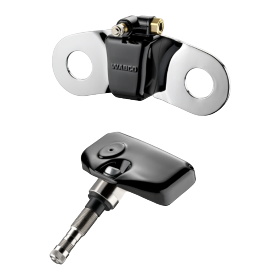
Components Components FIGURE NAME OF COMPONENT External wheel sensor (WM2) ECU bracket WABCO Display Balancing plate PA tube Adapter Wiring harness, truck Wiring harness, trailer (example) -
Page 11: Installation
Installation Installation Safety information – Observe the occupational health and safety regulations of the respective country, the workshop as well as the vehicle manufacturer’s instructions. Risk of accident due to loose wheel nuts Loose wheel nuts may lead to accidents when driving on roads. –... -
Page 12: Ecu
– Tighten ECU to bracket using torque of 15 ± 1.5 Nm. – Mount the bracket + ECU on the chassis. – Connect the ECU with the WABCO Trailer EBS modulator using the provided cable and the adapter. The provided cable may be routed along the same path as the current trailer... - Page 13 Installation Trailer wiring LEGEND ECU (via adapter cable with WABCO part number: 894 600 001 2) Brown: Ground Red: +12 V/24 V White: Stop light Diagnosis...
-
Page 14: Truck
– Connect the ECU to the vehicle using the provided cable and the adapter. – Fit the diagnostic socket to a suitable attachment location and label it with "Diagnostic OptiTire". – Install cables according to the wiring diagram using cable ties in parallel with... - Page 15 It is mandatory to use the additional adapter cable (not displayed in the illustration) LEGEND Display Diagnosis Vehicle electrical system ECU (via adapter cable with WABCO part number: 894 600 001 2) external internal Cable set assignment CONNECTOR PIN CABLE COLOUR CABLE COLOUR PIN NO.
-
Page 16: External Module & Balancing Plate
Installation External module & balancing plate Maintaining a list of the wheel module numbers and location on the vehicle is required for proper ECU programming: – Assign each wheel module to the designated wheel. – Enter each wheel module ID on the paper form (form can be found in the appendix of this manual). -
Page 17: Display
Display Comply with all safety and vehicle manufacture guidelines. – Determine where to install the WABCO display unit. The display housing is mounted with screws and the display is snapped into the housing. Modifications may be necessary to install this unit. -
Page 18: Ecu Programming
ECUs need to be programmed. – Turn on the vehicle ignition. – Connect the external diagnostic plug to the WABCO diagnostic interface using the diagnostic cable. – Select the vehicle type and type of diagnostic connection. It is also possible to automatically search for all connected ECUs (more time-consuming than the manual procedure). -
Page 19: Appendix
Appendix Appendix Wheel module ID numbers Make a record of wheel module ID numbers by noting the IDs and/or attaching ID stickers at each wheel location:... - Page 20 Appendix...
- Page 21 Appendix...
-
Page 22: Circuit Diagram
Appendix Circuit diagram... - Page 24 Founded solutions and aftermarket services. nearly 150 years ago, WABCO WABCO reported sales of $2.9 continues to pioneer breakthrough billion in 2014. The company products and systems for braking,...
Need help?
Do you have a question about the OptiTire and is the answer not in the manual?
Questions and answers