Advertisement
• We appreciate your commitment to Kohler quality. Please take a few minutes before you begin installation to review
this manual to become familiar with tools, materials and installation methods. If you encounter any installation or
performance problems, please don't hesitate to contact us. Thanks again for choosing Kohler Co.
• Please follow instructions closely to avoid costly mistakes caused by improper installation. Cover and protect the
components and fittings at all times during installation. Flush the plumbing lines before initial use.
• All information in this manual is based upon the latest product information available at the time of publication. Kohler
Co. reserves the rights to make changes in product characteristics, packaging or availability at any time without notice.
• Before continuing, please ensure there is no existing damage to the toilet and that there is suitable space for installation
with no interference with other bathroom fixtures such as shower door openings. Before proceeding with installation,
ensure there is ample room (approx 600mm) down each side of the pan to allow for servicing.
• To prevent serious damage, do not use corrosive solutions (see back page for care and cleaning information).
Any use of non-recommended products could void the Kohler warranty.
• This manual includes important care and cleaning information - please save these instructions.
COMPLIANCE
:
Ensure installation adheres to local building code & applicable plumbing/electrical standards.
• The Kohler Veil Intelligent Toilet - Wall Faced ( K-8423A-0 ) is WaterMark certified according to ATS 5200.051
Technical Specification for Plumbing and Drainage Products - Bidet Douche Seats.
• Installation must comply with AS/NZS 3500.1 Plumbing and Drainage - Water Services and AS/NZS 6400 Water
Efficient Products - Rating and Labelling.
Backflow Prevention
• The supplied Dual Check Valve is WaterMark certified according to AS 2845.1 Water Supply - Backflow Prevention
Devices - Materials, Design and Performance Requirements.
• Each site must have High Hazard Backflow Prevention installed upstream of the installation.
• For domestic installations, consult with a Licensed Practitioner (Plumber) before installation.
• For commercial applications, refer to a Hydraulic Consultant before specification or installation.
WARNING: Risk of electric shock. Disconnect power before servicing.
WARNING: Risk of electric shock. Connect only to a properly-grounded, grounding-type receptacle which is
protected by a Ground-Fault Circuit-Interrupter (GFCI) or Residual Current Device (RCD)
WARNING: Risk of electric shock. This product must be grounded. Connect only to a dedicated 220~240V AC,
50/60Hz circuit protected with grounded circuit-breaker or grounded electric leak circuit breaker
WARNING: 10A power supply is required.
Product Functions
• Hands-free flushing
• Manual dual-flush option
• Backflow prevention
Advantages for the In-wall Water Tank
• Anti-impact, rust-proof, macromolecule water tank reduces the possibility of leakages.
• Advanced water tank system is able to adjust 4.5/3 litre water discharge. To maintain the 4-star WELS rating, switch
off the Auto-flush option.
• No influence on wall structure, superb sound-proof effectiveness.
• Easy and quick installation saves time and labour.
• Easy servicing, wall reconstruction is not required.
• Sanitary system with no residual waste.
• Super thin tank body saves installation space and is applicable for all thin mounting walls.
Kohler Co.
Jan 2018
• Pre-set water inlet level & flush volume
• Suitable for either S-trap or P-trap installations
1
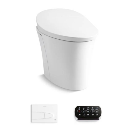
VEIL WALL FACED
INSTALLATION INSTRUCTIONS
INTELLIGENT TOILET
1345889-A02-A
K-8423A-0
Advertisement
Table of Contents

Related Manuals for Kohler VEIL WALL FACED


Summary of Contents for Kohler VEIL WALL FACED
- Page 1 fittings at all times during installation. Flush the plumbing lines before initial use. • All information in this manual is based upon the latest product information available at the time of publication. Kohler Co. reserves the rights to make changes in product characteristics, packaging or availability at any time without notice.
-
Page 2: Component Information
Unit:mm 478±3 13~62 438±3 88±2 Bidet water supply connector 45±3 Bidet water supply pipe 230±3 NOTE: S-trap installation shown as default. P-trap configuration is achievable by using a DN80 waste pipe connector. Kohler Co. Jan 2018 1345889-A02-A... - Page 3 Remote control Finished floor Finished floor Finished wall Toilet dimension drawing Fig.#2 Kohler reserves the right to change marked dimensions without prior notice. SPECIFICATION(8423A-0) 4.5L/3L 70kPa (Dynamic pressure) 740kPa (Static pressure) 220V~ , 50Hz 1000W 1600W 675mm x 438mm x 533mm (Height shall be calculated from floor to the top of the product)
- Page 4 A. Hold the edge of toilet bowl and slide out from packaging box. WARNING: Risk of product damage or personal injury. When lifting up the toilet, please hold it by the rim. Product is heavy, please employ a two-person lift. Fig.#4 Kohler Co. Jan 2018 1345889-A02-A...
- Page 5 WARNING: Bathtub and sprinkler head shall be far away from electrical parts (e.g. remote controller, power receptacle etc.) if it is wall-hung style, water proof or splash proof receptacle is required. If wall-mounting power supply is adopted, require anti-water and anti-splash power receptacle. Kohler Co. Jan 2018 1345889-A02-A...
- Page 6 IMPORTANT: Protect electronic connection point and wires from accidental damage. 1 metre height label (treat 1m as minimum). Recommended to install frame with 1m mark at 1020mm from floor. Hex key Bowl fixing holes Bidet water supply Adjustable support feet Bottom plate (nog) Kohler Co. Jan 2018 1345889-A02-A...
- Page 7 4. Tighten screw by wrench as shown in Fig A. Tighten screw by wrench as shown in Fig B. Socket Coach Wrench Screw Recommend M6x40 coach screw with 3mm washer. Socket Wrench Coach Screw Fig.#9 Kohler Co. Jan 2018 1345889-A02-A...
- Page 8 7. Place square cover within protection cover of water tank. Snap the buckle into the slot and tighten square cover bolts on tank. NOTE: Square cover has the word TOP on it indicating which surface should face upwards when installed. Fig.#11 Kohler Co. Jan 2018 1345889-A02-A...
- Page 9 Note: Do not lubricate the connection between pan and waste connector. Lubricate connection between waste connector and discharge elbow. Proceed to Step E on pg10. Bowl fixing hole Discharge elbow Bidet water supply Pan waste connector Bung Fig.#13 Kohler Co. Jan 2018 1345889-A02-A...
- Page 10 2. There may be significant amounts of dust when preparing the wall - be sure to fit dust cover over cistern opening and protect the electrical fittings and pipework. Finished wall Bowl fixing hole Square cover Cover the water inlet Pan waste connector Bung Fig.#15 Kohler Co. Jan 2018 1345889-A02-A...
- Page 11 2. Install the discharge pipe and water inlet pipe as shown. Place a ruler on the rear of the discharge pipe and water inlet, and use a pencil to mark the position. Adjust the space based on the rear of the toilet to wall discharge port. Water inlet pipe Discharge pipe Fig.#18 Kohler Co. Jan 2018 1345889-A02-A...
- Page 12 Apply grease to the discharge port to ease installation. CAUTION: Toilet is heavy, use a two person lift. Fixing bolt Bidet water supply M-F fitting Lubricant 90º bend Bidet water Bidet water supply hose supply hose Fig.#21 Kohler Co. Jan 2018 1345889-A02-A...
- Page 13 Green light OFF NOTE: Wiring order shall be L, N, Ground from top to bottom. L - Live wire N - Neutral wire - Grounding wire Fig.#24 Kohler Co. Jan 2018 1345889-A02-A...
-
Page 14: Water Level Adjustment
Fig.#26 Side panel Apply silicon gel G. Water Level adjustment 1. Follow the steps 6 to 11 on page 19 and 20 of this document to remove the water inlet valve. Water inlet valve Fig.#27 Kohler Co. Jan 2018 1345889-A02-A... -
Page 15: Control Panel Installation
Snap in position Slot A Locators Fig.#29 I. Top Button installation 1. When locating the four locknuts on supporting board, adjust to OPEN mark, as shown. Locknut Fixing lock Supporting board Fig.#30 Kohler Co. Jan 2018 1345889-A02-A... - Page 16 Install motor assembly signal wire and control panel signal Wire into U type hole of splash plate, as shown below. U type hole Supporting Cover board board Control panel signal wire Motor assembly signal wire Fig.#33 Kohler Co. Jan 2018 1345889-A02-A...
- Page 17 Dismantle motor assembly signal wire and control panel signal wire. Supporting Cover board board Snap in position Control panel signal wire Motor assembly signal wire Fig.#35 2. Unscrew two lag bolts as shown Bolt Lag bolt Bracket Fig.#36 Kohler Co. Jan 2018 1345889-A02-A...
- Page 18 All 4 lock nuts should align with the OPEN mark. Locknut Supporting board Fig.#37 4. Dismantle supporting board as shown. Supporting board Fig.#38 5. Pull water splash plate out Square cover Water splash plate Snap in position Fig.#39 Slot A Kohler Co. Jan 2018 1345889-A02-A...
- Page 19 7. Hold bracket top by hand as shown, then lift up to unlock the bracket. Bracket Fig.#41 8. Take discharge valve lever out from lag washers on both ends as shown. Lever clip Lag washer Fig.#42 Kohler Co. Jan 2018 1345889-A02-A...
- Page 20 Rotate valve switch to open/close water supply as shown. Valve Fig.#43 10. Loosen filter nut, as shown. Loose Tighten Filter Fig.#44 11. Remove the water inlet valve for cleaning or adjusting. Water inlet valve Fig.#45 Kohler Co. Jan 2018 1345889-A02-A...
- Page 21 It should make a “click” sound when installing or removing. Outlet Valve Fig.#47 14. Loosen discharge valve as shown and then take valve out for cleaning or adjusting. Outlet Valve Fig.#48 Kohler Co. Jan 2018 1345889-A02-A...
-
Page 22: Clean Filter
Inlet Valve Adjusting the control pole will cause the water level to Control Pole change within the water tank. Turn the pole clockwise to increase the water level and anti-clockwise to reduce it. Floating Box Fig.#51 Kohler Co. Jan 2018 1345889-A02-A... - Page 23 5. Fasten docking station with screws and place bushing on the bolts. Fig.#52 Steps of installation Public anti-loss installation Screw Hook board Lag bolt Lag bolt Remove rubber anchor plug Remove rubber Hook plug Docking station Remote control Fig.#53 Gasket Kohler Co. Jan 2018 1345889-A02-A...
-
Page 24: Troubleshooting
TROUBLE SHOOTING This troubleshooting guide is for general aid only. A Kohler Authorised Service Representative should correct any electrical problems. For warranty service, contact your dealer or wholesale distributor. Symptoms Probable Causes Recommended Action 1. Toilet does not work. A. A power failure occurred. - Page 25 TROUBLE SHOOTING (continued) This troubleshooting guide is for general aid only. A Kohler Authorised Service Representative should correct any electrical problems. For warranty service, contact your dealer or wholesale distributor. Symptoms Probable Causes Recommended Action 12. UV sterilisation A. Customer sits on seat.
-
Page 26: Contact And Warranty Information
Most toilet cleaners are not harmful to eh vitreous china surface of the toilet pan. Kohler Co. does not recommend the use of any cleaning products which are submerged in the cistern as the acids contained within the cleaner will prematurely deteriorate gaskets and valve parts.
Need help?
Do you have a question about the VEIL WALL FACED and is the answer not in the manual?
Questions and answers