Table of Contents
Advertisement
Quick Links
System Overview
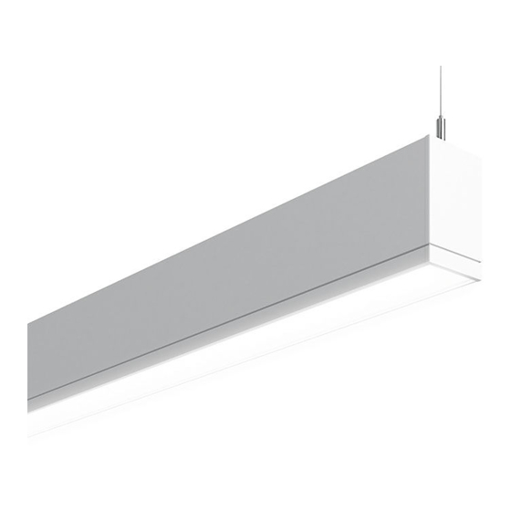
These instructions review how to install TruGroove Perimeter Ambient and Graze fixtures. Modules can be installed as individual
standalone units, or they can be joined together to create continuous runs. The graphics below show the components required to
install a typical run of TruGroove Perimeter fixtures. IMPORTANT: Read all instructions before beginning installation.
Wall Rail
On Grid End Set
On-grid endplate left (x1)
On-grid endplate right (x1)
#8 sheet metal screws (x6)
!
ATTENTION: Install in accordance with national and local building and electrical codes.
Joiner Kit
Joiner bracket (x1)
Biscuit aligners (x2)
#8 sheet metal screws (x2)
Mount Spacing & Power Feed Location
TruGroove Perimeter modules are designed for exact on-grid mounting. 2 mount-
ing and 2 power feed locations are available on each module. Refer to layout draw-
ings or row configuration documents for module lengths and mounting distances.
Grid Panel Kit
Grid panel (x1)
Grid clips (x2)
#8 sheet metal screws (x3)
Tools Required:
Phillips Screwdriver
Variable End Set
Variable endplate left (x1)
Variable endplate right (x1)
Variable panels (x2)
On-grid end caps (x2)
Grid clips (x2)
#8 sheet metal screws (x8)
#2 Robertson Screwdriver
Page 1
Advertisement
Table of Contents

Related Manuals for Philips LEDALITE TruGroove Series


Summary of Contents for Philips LEDALITE TruGroove Series
-
Page 1: System Overview
System Overview These instructions review how to install TruGroove Perimeter Ambient and Graze fixtures. Modules can be installed as individual standalone units, or they can be joined together to create continuous runs. The graphics below show the components required to install a typical run of TruGroove Perimeter fixtures. - Page 2 Ceiling Preparation Ceiling Preparation Wall Rail Installation 4” Regress Wall Rail Installation 2” Regress (Flat Wall) (Textured Wall) Suspension Suspension Wall rail Wall rail cable cable Bottom Flat Flat edge of wall wall shown installed shown fixture Ceiling preparation covers grid ceiling modifica- Optional: Textured walls.
- Page 3 Fixture Installation Fixture Installation Power Feed Connection Fixture Joining 5⁰ max. cable deviation from vertical Remove packaging insert Release tab Graze shown Graze shown Engage housing on wall rail. Insert suspension cables To adjust fixture level, support bottom of housing Break 7/8”...
- Page 4 Variable End Installation Variable End Installation Flat End Installation Variable End Installation NOTE: Installed flat endplate orientation Trim endplate as needed Check that endplate edge is flush with housing and After fixture modules have been installed and lev- After variable endplate has been trimmed to size, IMPORTANT: Flat endplate must be oriented and slide endplate toward wall guiding open slots to- attach final screw to lock in place.
- Page 5 Panel Installation Variable Panel Installation Variable Panel Installation Variable Panel Installation Optional Wall Wall (not shown for clarity) (not shown for clarity) Secure variable panel to housing with screw For variable ends on-grid, insert variable panel Secure grid clips to t-bar ceiling using screws For variable ends at a wall, insert variable panel (by others).
Need help?
Do you have a question about the LEDALITE TruGroove Series and is the answer not in the manual?
Questions and answers