Ronan Engineering X96S Instructions And Operating Manual
Level gauge
Hide thumbs
Also See for X96S:
- Instructions and operating manual (68 pages) ,
- Instructions and operating manual (77 pages) ,
- Instructions and operating manual (68 pages)
Table of Contents
Advertisement
Quick Links
Advertisement
Table of Contents

Related Manuals for Ronan Engineering X96S


Summary of Contents for Ronan Engineering X96S
- Page 1 Instructions Operating Manual X96S LEVEL GAUGE RONAN ENGINEERING COMPANY – MEASUREMENTS DIVISION 8050 Production Drive Florence, KY 41042 Phone: (859) 342‐8500 Fax: (859) 342‐6426 Website: www.ronan.com E‐mail: ronan@ronanmeasure.com ...
-
Page 2: Table Of Contents
Table of Contents OVERVIEW ..................................1 Advantages ..................................1 Gamma's Advantages ..............................1 X96S Advantages ................................1 BASIC CONCEPTS ................................2 Communications ................................2 4-20 MA ..................................2 HART ..................................... 2 Variables .................................... 2 Communication Variables .............................. 2 Device Variables ................................2 Configuration Variables .............................. - Page 3 X96S LOCAL DISPLAY ..............................27 Navigating Menus ................................28 Editing Values .................................. 28 Editing Fixed Point Numbers ............................28 Editing Floating Point Numbers ........................... 28 Editing Text Strings ..............................28 Editing Enumerated Values ............................29 X96 Local Display Vs 275 Calibrator ..........................29 INSTALLATION ................................
-
Page 4: Overview
Overview The X96S is a family of measurement products that is intended to replace the obsolete X96N and current X99 product families. These products: use nuclear measurement techniques, support all features of the obsolete X96N and current X99 products, ... -
Page 5: Basic Concepts
The Ronan X96S Level gage has 2 device variables: Device Variable Value Level Level Head Temp Head Temperature Configuration Variables The Ronan X96S Level gage has many configuration variables that are accessed through its menus. RONAN ENGINEERING COMPANY – MEASUREMENTS DIVISION 8050 Production Drive Florence, KY 41042 ... -
Page 6: Theory
LOW output of counts. The X96S Microprocessor converts the detector signal to user's measurement units of level: m, mm, cm, in, ft. The X96S displays the output measurement range in the selected user units. The "zero" of the measurement range represents the lowest level of interest, while the "span"... -
Page 7: Principles Of Operation
The Calibration (or Referencing) procedure relates detector output (in counts) to numeric values that accurately represent the actual process level. The level algorithm used by the X96S software is a simple transfer function. That is, the relationship between the detector output and the process level is mathematically expressed as: ... -
Page 8: Password
Password Notice: To access the Programming Menu, the Password is 101010. Step 1: Power Up – You should now be on the Status Screen. Step 2: Press F3 to go back. Step 3: Now enter the password. (All digits are set at 000000 at this point.) Press to get the digit to be # one Press... -
Page 9: Menus/Operation
Menus/Operation Menu Trees The Ronan X96S Level Gauge uses a tree structured menu system. Ronan X96S – Level Variables Variables Status Display Configuration Variable Mapping Variable Mapping Digital Outputs PV [value units] Digital Inputs SV [value units] PV is [var mapped to PV]... - Page 10 Configuration Operation Operation Level Config Head Temp Config Filtering Filtering Alarms Detector Fault Hardware Linearization Type HART Scan Time [ms] Dyn Track [enable/disable] System Sigma [value] Fast TC [seconds] Fast Counter [value] Medium TC [seconds] Level Config Slow Counter [value] Slow TC [seconds] Units [units] Noise Filter [0]...
- Page 11 Continued from previous page Configuration Operation Alarm (number) Level Config Head Temp Config Source [variable] Alarms Alarm Type [variable] Hardware Alarms Setpoint [SGU] HART Alarm 1 Setpoint 2 [SGU] System Alarm 2 Hysterisis [%] Alarm 3 Alarm 4 Alarm on 4-20mA Alarm 5 None Alarm 6...
- Page 12 Continued from previous page Configuration Hardware (Cont’d) Operation System Hardware Level Config Source Type Head Temp Config Analog Out Config Alarms Flow Hardware [read only] Hardware Com1 Protocol Analog Out Config Hart System Loop 1 (PV) [variable] Loop 2 (SV) [variable] HART Loop 3 (TV) [variable] Power Source [int/ext]...
- Page 13 Digital Outputs Output [select] Output Relay 1 Select Sources Relay 2 Polarity Relay 3 Relay 4 TTL 1 TTL 2 TTL 3 TTL 4 Select Sources Output [type] Output Alarm 1 [yes/no] [select] Alarm 2 [yes/no] Relay 1 Alarm 3 [yes/no] Relay 2 Alarm 4 [yes/no] Relay 3...
- Page 14 Auto Cal Auto Cal Setup Auto Cal 1…8 Auto Cal Setup Auto Cal 1 Auto Cal [Enable/Disable] AutoCal Capture Auto Cal 2 Level [value] Auto Cal Status Auto Cal 3 Trigger Delay [value]sec Auto Cal 4 Source Auto Cal 5 AC1 State [Read only] Auto Cal 6 Auto Cal 7...
- Page 15 Calibration State [status] Ref Constants Ref Constants Calibrate Last Ref Date [date] Ref Mode [variable] Last Ref Time [time] Calibr. Mode [variable] Loop Config Ref Time [seconds] Aux Loop Cfg Min Ref Cnts [counts] Max Ref Cnts [counts] Calibrate Low Reference Low Reference Perform Low Cal High Calibrate...
-
Page 16: Root Menu
Root Menu The root menu is titled “Ronan X96S – Level”. It contains the following items: ITEM FUNCTION Variables Selecting this choice takes the user to the Variables menu Displays Selecting this choice takes the user to the Displays menu... -
Page 17: Status Display Menu
Status Display Menu The Status Display menu is used to configure the device status display. It contains the following items and allow the user to change the selection: ITEM FUNCTION Analog Bar Shows the current state of the analog bar display (enabled or disabled) and allows the user change the state. -
Page 18: Operation Menu
Operation Menu The Operation menu is used to access the menus and variables that control the processing of the level data. It contains the following items: ITEM FUNCTION Filtering Selecting this choice takes the user to the Filtering menu Detector Fault Selecting this choice takes the user to the Detector Fault menu Linearization Selecting this choice takes the user to the Linearization menu... -
Page 19: Linearization Menu
Linearization Menu The X96S can perform a multi-point linearization of the density data when required by an application. The linearization table contains 32 entries, numbered 1 through 32. Each entry consists of a measured value, an actual value, and a flag that indicates if the entry is used The Linearization menu is used to control the linearization mechanism. -
Page 20: Head Temp Config Menu
Units is one of the following: Units MEANING feet meter inch centimeter millimeter Head Temp Config Menu The Head Temp Config menu is used to configure the parameters associated with the detector electronics temperature measurement. This function is used primarily in high-temperature applications where the temperature exceeds the electronics temperature specifications. -
Page 21: Hardware Menu
Alarm Type (Alarm 4-20 mA only) only occurs under one of the following three conditions: 1) System Failure 2) Empty Pipe Clamp 3) Detector Faults The 4-20 mA output can be configured as one of the following if in “alarm” conditions: ITEM MEANING None... -
Page 22: Source Type Menu
Source Type Menu The Source Type menu is used to define the type of radiation source used. It contains the following items: ITEM FUNCTION Source Type Shows and allows the user to set the source type Usr Def Source Selecting this takes the user to the User Def Source menu Next Reference Shows the date of when the next Reference should be completed Next Wipe Test... -
Page 23: System Menu
Relay and TTL Menus The Relay and TTL menus are used to configure the X96S Relay Outputs and the 4 TTL Outputs. The Relay and TTL menus show the settings of the corresponding 4 Relay Outputs and 4 TTL Outputs, allowing the characteristics of the outputs to be changed. -
Page 24: Digital Inputs
Select sources has the following options to assign: ITEM FUNCTION Alarm 1 Allows the user to assign Alarm 1 to the selected digital output [yes/no] Alarm 2 Allows the user to assign Alarm 2 to the selected digital output [yes/no] Alarm 3 Allows the user to assign Alarm 3 to the selected digital output [yes/no]... -
Page 25: Ttl Menus22
TTL Menus The TTL menus (TTL 1 through TTL 4) are used to configure the X96S TTL outputs. These four TTL menus show the settings of the corresponding TTL output and allow the characteristics of the output to be changed. Each menu... -
Page 26: Digital Inputs Menu
Digital Inputs Menu This menu is used to view and configure the digital inputs. It contains the following item: ITEM FUNCTION Input 1 Selecting this item takes the user to the Input 1 menu Input 2 Selecting this item takes the user to the Input 2 menu Input 3 Selecting this item takes the user to the Input 3 menu Input 4... - Page 27 Auto Cal Setup is used configured the 8 Auto Cal points. It contains the following: ITEM FUNCTION Auto Cal 1 Selecting this item takes the user to the Auto Cal 1 menu Auto Cal 2 Selecting this item takes the user to the Auto Cal 2 menu Auto Cal 3 Selecting this item takes the user to the Auto Cal 3 menu Auto Cal 4...
-
Page 28: Calibration Menu
Calibration Menu This menu is used to view and control the calibration of the X96S Level Gage. It contains the following items: ITEM FUNCTION State Shows the state of the level configuration process Ref Constants Selecting this item takes the user to the Ref Constants menu... -
Page 29: Low Reference Menu
Diagnostics ITEM FUNCTION Raw Counts Non-filtered counts from the detector Filt Counts X96S filtered counts from the detector Raw Dens. Displays the real time raw density value Current Displays the real time 4-20ma value Ref/Cal Data Displays the information on the reference/calibration data... -
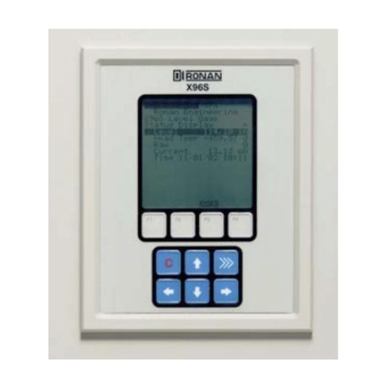
Page 30: X96S Local Display
X96S Local Display X96S The X96S Local Display consists of 8 lines by 21-character 30% display, and a 10-key keypad. The top line of the display is Ronan Engineering reserved for the analog bar, if enabled. The next line is used for X96S Density Gauge the Ronan logo. -
Page 31: Navigating Menus
Navigating Menus The menu and the display screen are one or more lines, each consisting of a line label (name of the entry) and optional value and units. In most cases the menu navigation is exactly following the Rosemount 275 Configurator’s user interface. -
Page 32: Editing Enumerated Values
Editing Enumerated Values The enumerated values are displayed as menu items below the current value. The up and down arrow keys are used to select the desired choice, and F4 is used to confirm it. F3 is used to abort the editing and leave the value unchanged. -
Page 33: Installation
Installation Ronan's Monitor Systems use a sealed radioactive cesium (Cs-137) source which is safe if handled Caution properly. Most Level Monitors are mounted to large vessels. Installations on vessels that permit personnel access require a specific license. Your company's specific Specific License license will name a Radiation Safety Officer (RSO) or (SA or GS Series) - Page 34 Inspection The source holder is equipped with an ON/OFF mechanism. During shipment and storage the mechanism MUST BE SECURED in the OFF position with a padlock. Radiation Label If the padlock is damaged, broken, or missing, contact the RSO immediately. Handle Padlocked OFF General License Label (if applicable)
-
Page 35: Safety Precautions
Safety Precautions During installation the RSO will provide guidelines to assure safety. Consider the information presented in the Regulation/Safety Chapter of this manual, as well as the following general guidelines: The source holder must remain padlocked in the OFF position until installation is complete. Take all necessary precautions to assure that the source holder is not dropped or damaged. -
Page 36: Mechanical Mounting
Mechanical Mounting Review the Configuration Drawing which is included in the Drawing Chapter of this manual. Please reference the dimensional drawings located in the Drawing Chapter of this manual when installing the equipment. Consider the following general guidelines when Drawings mounting the sensor and detector: Avoid internal vessel obstructions such as baffles, agitators, manways, heater/cooler tubes, etc. -
Page 37: Electrical Installation Of Interconnect Wiring
Electrical Installation of Interconnect Wiring DO NOT APPLY POWER until wiring is carefully checked. Wire the equipment according to the detailed interconnect drawing which is included in the Drawings Drawing Chapter of this manual. Follow local and national electrical codes for all interconnections. -
Page 38: Microprocessor Verification
These boards are not interchangeable in the frame’s slots. Identification / Documentation The Ronan X96S Microprocessor can be programmed for a variety of applications and configurations. The specific application supplied with each system is determined by the combination of software and the unique hardware configuration used to support the software. -
Page 39: Power-Up
Power-up X96S Before applying power, ensure all boards are fully Ronan Engineering seated in frame’s slots. Close front door of the X96S Please, wait…. and secure the door... When power is applied the X96S runs a self-diagnostic program First display appears for just a second To adjust the contrast on the LCD display: Press the “C”... -
Page 40: Password
Password Notice: To access the Programming Menu, the Password is 101010. Step 1: Power Up – You should now be on the Status Screen. Step 2: Press F3 to go back. Step 3: Now enter the password. (All digits are set at 000000 at this point.) Press to get the digit to be # one Press... -
Page 41: Calibration
Calibration Calibration correlates the X96S's output to your actual process level. It instructs the microprocessor to read and store the detector counts for a low and high level of process. Once the system is conditioned to recognize the low and high level, it will provide a 4-20 mA output over the entire range of interest. - Page 42 Step 1 Start at the Status Display Ronan Engineering From the Status Display Screen, Press the F3 Key to display the X96S Level Gage Status Display Password Screen (or the Main Menus if the password is disabled). Level 4.7500 in Head Temp 92.00 degF...
- Page 43 Low Calibration (Have the vessel empty or low as possible under normal operations) Ronan Engineering Scroll down to “Calibration” Press the Enter Key X96S Level Gage Scroll down to “Calibrate” Press the Enter Key Main Menu Variables Scroll down ...
- Page 44 (Fill vessel to 100% of range or close source shutter to represent full) Scroll down to “Calibration” Press the Enter Key Ronan Engineering Scroll down to “Calibrate” Press the Enter Key X96S Level Gage Scroll down to “High Calibrate” Press the Enter Key Main Menu Variables Select “Perform High Cal”...
-
Page 45: Documentation
After installation at your site, you may need to reconfigure the system to fit your application. The goal is to correlate the X96S output with your actual level readings. The list below summarizes the activities that are detailed in the remainder of this chapter: - Check the factory-default settings to be sure they are appropriate for your circumstances. -
Page 46: Detector
Detector Scintillator Detector Description The Ronan scintillation detector consists of three main components: The plastic scintillation crystal, the photo-multiplier tube (PMT), and the associated electronics. Scintillation Crystal The crystal used for the Level System is poly-vinyl toluene (PVT) plastic. The crystal produces light pulses which are proportional to the incident radiation events striking it. - Page 47 Detector Service The critical components of the electronic circuit and the PMT/Crystal Assembly are aligned before leaving the factory. If any component of the Scintillation Detector is adjusted or replaced, the performance of the entire system will be adversely affected and will require realignment before continued use is possible. Therefore, the scintillation detector IS NOT field serviceable.
-
Page 48: Ion Chamber
10A, so an electrometer amplifier (DET-7471-XXX) is required to convert the current to a low-impedance, high level voltage signal. The signal is then measured by the X96S Microprocessor, which converts the voltage signal to a output of 4-20mA for a specified measuring range. -
Page 49: Detector Housing
Detector Removal/ Replacement 1) Check NOTES below for illustrations and cautions that apply to your specific equipment. 2) Unscrew cap on detector housing. Detector Housing Cap 3) Unscrew connector on top of detector. Detector Housing Cable Connector 4) Remove detector from housing. 5) Carefully install replacement detector in Detector housing. - Page 50 Removing the Detector Amplifier Circuit Board Follow this procedure to remove the electrometer amplifier circuit CBAY-6102 board: 1. Remove the amplifier cover by unscrewing the hex socket head cap screws. 2. Remove the MS connector from the amplifier cover. 3. Remove the two 6-32 binding head screws, which secure the amplifier board to the detector.
-
Page 51: Electronics
Electronics X96-2001PL X96-2001PL is a CPU Module that comes without software. X96-2002PL X96-2002PL is the local Graphics L.C.D. Module. This optional module provides: Graphic LCD Keypad X96-2003PL X96-2003PL is the Ionization Chamber Interface Module. This optional module provides: ... - Page 52 X96-2008PL X96-2008PL is the Digital Input/Output Module. The module provides a total of 16 bits of digital I/O and wetting/encoder power. 8 isolated digital inputs are provided. These inputs can be configured for use as: dry or live contact monitoring, ...
- Page 53 X96-2009PL2 X96-2009PL is the Scintillation Detector Interface Module. This optional module provides: 1 isolated scintillation input (pulse counter, max signal 0-12 V, threshold 0.6 V) 1 head temperature input (1 uA per deg K) a 4-20 mA input (Ch. 2) ...
- Page 54 X96S-N4X, NEMA 4X, 6 Position, W/O LCD Display, Stainless CHAS-0514-9-SS X96S-N4X, NEMA 4X, 9 Position, W/O LCD Display, Stainless CHAS-0515-6-SSW X96S-N4X, NEMA 4X, 6 Position, W/O LCD Display, With Window CHAS-0516-9-SSW X96S-N4X, NEMA 4X, 9 Position, W/O LCD Display, With Window X96C429-1 LCD Display Assembly “Local”...
- Page 55 SPECIFICATINS MODEL X96S Process Computer: Microprocessor-based unit with a liquid crystal display, push-button interface, HART Communications, process control outputs, process condition inputs, serial communications. Chassis: 19” rack mount, surface mount, or panel mount. Enclosure: Standard NEMA-4 Stainless Steel NEMA-4X...
-
Page 56: Sample Drawings
SAMPLE DRAWINGS SERIES X96S-N4 X96S Sample drawing only. See the drawing section of your packet for specifics. RONAN ENGINEERING COMPANY – MEASUREMENTS DIVISION 8050 Production Drive Florence, KY 41042 Phone: (859) 342‐8500 Fax: (859) 342‐6426 Website: www.ronan.com E‐mail: ronan@ronanmeasure.com Updated 09‐25‐2017 ... - Page 57 RONAN ENGINEERING COMPANY – MEASUREMENTS DIVISION 8050 Production Drive Florence, KY 41042 Phone: (859) 342‐8500 Fax: (859) 342‐6426 Website: www.ronan.com E‐mail: ronan@ronanmeasure.com Updated 09‐25‐2017 ...
Need help?
Do you have a question about the X96S and is the answer not in the manual?
Questions and answers